


75
PDR-W839
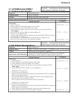
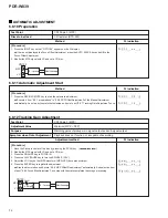
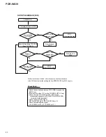
[Procedure]
1. Move the Pickup to center of the disc by pressing the SCAN key. (
41 ¡¢
)
2. Monitor the jitter value and set a CD disc. (use the jitter meter)
3. Press the FINALIZE key to FOCUS IN.
4. Press the PLAY/PAUSE key to turn the SPINDLE. (CAV)
5. Press the PLAY/PAUSE key to TRACKING ON. (EFM CLV)
6. Adjust the JOG key so that jitter value becomes minimum.
7. Press the ENTER key to register the adjustment.
\
Shift to the RFDC Level Adjustment automatically.
8. Adjustment is completed automatically.
\
Each display the reason that became abnormal when adjustment was not completed normally.
When did not converge in limit of adjustment possibility
(when it became the lowest level)
When failed in writing to the EEPROM
9. Press the STOP key to stop the operation.
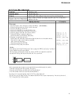
Caution:
In this adjustment, shift to the RFDC Adjustment when pressing the ENTER key before step 7, and there is
it when completed in normal on the indication.
However, must not omit operation of steps 5 from 3 because RFDC is not adjusted to normal when
pressing the ENTER key with the state that steps 5 from 3 are not executed.
How to execute the automatic adjustment once again after the automatic adjustment is completed:
1. Press the STOP key to stop the disc rotation. (servo OFF)
2. Press the AUTO SPACE key and shift to the Focus Offset adjustment.
3. Press the REC/REC MUTE key to start the automatic adjustment.
Adjust from "6.8.11 automatic Adjustment Start" to "6.8.13 Focus Bias Adjustment".
Press the STOP key when stops execution of the automatic adjustment on the way and stop processing. Then return to the state of
"6.8.10 Preparations" and stop the operation.
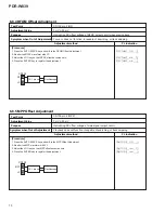
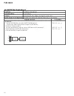
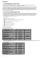
6.8.13 Focus Bias Adjustment
Minimize jitter value
CN102-pin 2 (RF)
Test Point
Adjustment Value
Focus-in does not function, sound pauses, bad RF wave form, or incapable of
playing some discs.
Optimizing DC offset voltage of focus servo loop circuit including pickup.
Purpose
Symptom when Out of Adjustment
Adjustment method
FL Indication
CN102
RF
VC
2
6
10: 1 prove
Oscilloscope
Содержание PDR-W839
Страница 21: ...PDR W839 21 A B C D 5 6 7 8 5 6 7 8 3 5 A A 1 5 A 2 5 A 4 5 A 1 5 Servo Amp IC Multiplexer ...
Страница 22: ...PDR W839 22 A B C D 1 2 3 4 1 2 3 4 4 5 A EFM ENCODER A 1 5 A 5 5 A 1 5 OP CO 23 24 3 6 CD R CORE ASSY 4 5 ...
Страница 39: ...PDR W839 39 ...
Страница 50: ...PDR W839 50 A B C D 1 2 3 4 1 2 3 4 4 5 MAIN ASSY H MAIN ASSY H CN1201 D CN701 I To POWER SUPPLY ASSY CN1301 L ...
Страница 51: ...PDR W839 51 A B C D 5 6 7 8 5 6 7 8 H PNP1480 C SIDE A CN502 A 301 CN302 A ...
Страница 53: ...PDR W839 53 A B C D 5 6 7 8 5 6 7 8 H IC601 Q492 Q401 Q428 IC1811 IC901 Q490 Q481 1 SIDE B ...
Страница 55: ...PDR W839 55 A B C D 5 6 7 8 5 6 7 8 I L HEAD PHONE ASSY L OPERATING1 ASSY I CN801 H CN901 H To Key Board ...
Страница 56: ...PDR W839 56 A B C D 1 2 3 4 1 2 3 4 I L HEAD PHONE ASSY L OPERATING1 ASSY I IC701 Q708 ...
Страница 94: ...94 PDR W839 Pin Function 1 5 PDC069 CD R CORE ASSY IC501 Encoder IC ...
Страница 95: ...95 PDR W839 Pin Function 2 5 ...
Страница 96: ...96 PDR W839 Pin Function 3 5 ...
Страница 97: ...97 PDR W839 Pin Function 4 5 ...
Страница 98: ...98 PDR W839 Pin Function 5 5 ...
Страница 103: ...103 PDR W839 ...


