background image

6

Françias

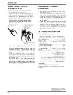
Installer l'appareil marqué "DROITE" du côté droit de l'écran
de visualisation.

Ecran d’affichage
au plasma

1

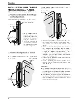
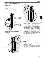
Fixer les accessoires de montage
aux haut-parleurs.

L’illustration ci-dessous représente le haut-parleur droit.

Pour côté
supérieur

Plaque de montage

Vis à tête fraisée
plate

1

Les accessoires destinés à

la partie supérieure sont
différents pour les côtés

droit et gauche et doivent

être parfaitement assortis.

2

Installer les accessoires de

montage avec des boulons

aux emplacements indiqués
dans la figure à gauche.

Pour le bas

Vis à tête
hexagonale noyée

Vis à tête
hexagonale noyée

INSTALLATION SUR ÉCRAN DE
VISUALISATION AU PLASMA

Effectuer l'installation selon les étapes 

1

 à 

2

 suivantes.

2

Fixer les haut-parleurs à l’écran.

Installer l'appareil marqué "GAUCHE" du côté gauche de
l'écran de visualisation.

1

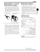
Pour fixer les haut-parleurs à l’écran, placer d’abord la vis

supérieure à l’endroit indiqué et la serrer jusqu’à ce qu’il

reste un espace d’environ 5 mm entre la tête de la vis et
l’écran.

2

Vérifier les indications LEFT (gauche) et RIGHT (droite),

sur la face arrière des haut-parleurs, pour s’assurer que
le haut-parleur est fixé sur le côté qui lui correspond.

S’assurer que le repère UP (haut) est orienté vers le haut,

puis fixer le haut-parleur en glissant l’accessoire de mon-
tage supérieur sur la tête de la vis et en le faisant coulisser

jusqu’à ce qu’il soit bien fixé.

3

Apposez l’ajustage de précision inférieur à l’écran et serrez
la vis à environ mi-chemin.

4

Ajuster la position de façon que le jeu entre l’enceinte
acoustique et l’écran d’affichage soit constant, et ensuite serrer
fermement les vis.

REMARQUE:

÷

Si l’écran d’affichage doit être déplacé après l’installation
de l’enceinte acoustique, ne pas soulever l’écran
d’affichage en tenant l’enceinte acoustique. Tenir plutôt
l’écran d’affichage par-dessous pour le déplacer.

÷

Les enjoliveurs frontaux sont conçus pour protéger les
haut-parleurs. Cependant, un effort excessif (comme une
pression sur la grille ou l’insertion d’objets à travers de
celle-ci) peut les endommager.

Ecran d’affichage
au plasma

Содержание PDP-S06-LR

Страница 1: ...structions Mode d emploi Bedienungsanleitung Istruzioni per l uso Gebruiksaanwijzing Manual de instrucciones Speaker System Enceintes acoustiques Lautsprechersystem Sistema di diffusori Luidsprekersysteem Sistema de altavoces ...

Страница 2: ...ufficient care as the grille net and the cabinet can become damaged or broken when they are subjected to strong external impacts Placing a CRT computer screen or CRT monitor near to the speakers may result in interference or color distor tion If this happens distance the monitor from the speak ers CAUTION This product is designed exclusively for use with the PDP 5030HD PDP 503HDE PDP 503HDG Pionee...

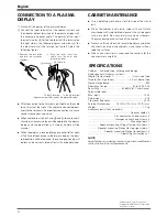
Страница 3: ...of the display For bottom Hexagon socket head screw 1 To attach the speakers to the display start by placing the upper screw where indicated tightening until there is a small space of about 5mm between the head of the screw and the display 2 Check the rear of the speakers for the LEFT and RIGHT indicators to make sure you are attaching the correct speaker to the corresponding right or left side Ma...

Страница 4: ...he input terminals of the speaker system and the speaker output terminals of the plasma display with the accessory speaker cable The polarity of the input terminals is plus ª for the red terminal the terminal on the right side in the following figure and minus for the black terminal the terminal on the left side in the following figure To the terminal To the ª terminal Speaker output terminals of ...

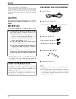
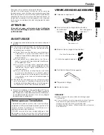
Страница 5: ...utrement l enjoliveur frontal et le coffret risqueraient d être endommagés ou hors d usage en les soumettant à des chocs externes exagérés Ce produit est conçu exclusivement pour l utilisation avec un écran d affichage au plasma Pioneer PDP 5030HD ou PDP 503HDE 7 Accessoires de montage de haut parleur 7 Boulons de montage de haut parleur Pour côté droit supérieur x 1 Pour côté gauche supérieur x 1...
Страница 6: ... à ce qu il reste un espace d environ 5 mm entre la tête de la vis et l écran 2 Vérifier les indications LEFT gauche et RIGHT droite sur la face arrière des haut parleurs pour s assurer que le haut parleur est fixé sur le côté qui lui correspond S assurer que le repère UP haut est orienté vers le haut puis fixer le haut parleur en glissant l accessoire de mon tage supérieur sur la tête de la vis e...

Страница 7: ...vement aux bornes Une connexion défectueuse risque de causer des parasites ou des coupures de son Si des brins s échappant du câble causent un court circuit entre les circuits ª et l écran d affichage au plasma recevra une charge excessive et risque de ne plus fonctionner ou d être endommagé Si la polarité est inversée sur un haut parleur gauche ou droit lors du branchement de l écran d affichage ...

Страница 8: ... führt zu einer Verstärkung des Klirrfaktors außerdem kann eine Beschädigung der Lautsprecher die Folge sein Die Lautsprecher sind vorsichtig zu behandeln da Ziergitter und Gehäuse durch starke Stöße und Erschütterungen verkratzt bzw beschädigt werden können HINWEIS Zur Installation der Lautsprecher stets die als Zubehör mitgelieferten Befestigungsteile verwenden Wenn andere als die mitgelieferten...

Страница 9: ...ach können die Schrauben gut festgezogen werden INSTALLATION DES PLASMA DISPLAYS Die Installation entsprechend den nachfolgenden Schritten 1 bis 2 vornehmen 1 Die Montagehalterungen an den Lautsprechern anbringen Die Abbildung zeigt den rechten Lautsprecher Für obere Seite Montageplatte Flachkopfschraube 1 Da sich die oberen Halterungen des rechten und linken Lautsprechers unterscheiden ist auf ko...

Страница 10: ...er Konuslautsprecher x 2 Hochtöner für hohe Frequenzen 2 5 cm Kuppellautsprecher Nennimpedanz 8 Ohm Frequenzbereich 50 bis 20 000 Hz Empfindlichkeit 82 dB W bei 1 m Abstand Zulässige Eingangswerte Maximaler Eingangswert 12 W Nenn Eingangswert 4 W Übergangsfrequenz 3 kHz Äußere Abmessungen 74 B x 714 H x 101 T mm Gewicht 1 7 kg Zubehörteile für 2 Lautsprecher Lautsprecherkabel x 2 Flachkopfschraube...

Страница 11: ...giarsi Si prega di maneggiare con cura gli altoparlanti la griglia di schermo e la cassa esterna possono danneggiarsi o rompersi se sottoposte a colpi esterni molto forti CONTROLLO DEGLI ACCESSORI IN DOTAZIONE 7 Cavo altoparlanti x 2 7 Accessori per il montaggio degli altoparlanti 7 Bulloni per il montaggio degli altoparlanti 7 Attrezzo per il montaggio Chiave esagonale 7 Istruzioniperl uso NOTA P...

Страница 12: ...afferrarlo per la parte bassa Display a plasma INSTALLAZIONE SUL DISPLAY A PLASMA Effettuare l installazione seguendo i passi da 1 a 2 descritti nel seguito 1 Fissare i sostegni di montaggio agli altoparlanti L illustrazione mostra l altoparlante destro Per il lato superiore Piastra di montaggio Vite piatta a testa conica 1 Gli accessori sinistro e destro del lato superiore sono diversi e devono q...

Страница 13: ...oni senza preavviso per il miglioramento del prodotto DATI TECNICI 1 Disinserire l alimentazione del display al plasma 2 Collegare i terminali di ingresso degli altoparlanti ai terminali di uscita per gli altoparlanti del display al plasma mediante l apposito cavo fornito con gli accessori La polarità dei terminali d ingresso è più ª nel caso del terminale rosso il terminale a destra nella figura ...
Страница 14: ...rekersysteem kunnen beschadigen Wees uitermate voorzichtig met de luidsprekers Het rooster en de behuizing zouden kunnen worden beschadigd wanneer het luidsprekersysteem aan schokken of stoten onderhevig wordt gesteld CONTROLEREN VAN DE ACCESSOIRES 7 Luidsprekerkabel x 2 7 Luidspreker montagebeugels 7 Luidspreker montagebouten Platte verzonken schroef x 4 Zeshoekige schroef x 4 Voor de rechter bov...

Страница 15: ...racht op uit b v niet op het rooster drukken of er voorwerpen insteken om beschadiging te voorkomen Nederlands Plasma display Nederlands 1 De bovenste montagedelen zijn voor de rechter en de linkerkant verschillend Zorg ervoor dat u ze juist bevestigt 2 nstalleer de montagebeugels met bouten op de plekken zoals aangegeven in de afbeelding links 1 Om de luidsprekers aan het scherm te bevestigen pla...

Страница 16: ...delen de behuizing aantast Bij gebruik van een chemische doek moet u alvorens gebruik de aanwijzingen goed lezen en controleren of deze doek voor dit systeem geschikt is TECHNISCHE GEGEVENS Behuizing Afgesloten Luidsprekers tweewegsysteem Woofer voor lage tonen Ovaal hoornvormig type x 2 Tweeter voor hoge tonen 2 5 cm koepelvormig type Nominale impedantie 8 Ohm Frequentiebereik 50 t m 20 000 Hz Ge...

Страница 17: ...r daños al sistema de altavoces de una sobrecarga de entrada tenga en cuenta las precauciones siguientes No suministre alimentación al sistema de altavoces excediendo de la máxima entrada permisible Esto podría dar lugar a daños en el sistema o riesgo de incendio Cuando conecte o desconecte los enchufes de clavija cerciórese de que la alimentación del amplificador se encuentra desactivada OFF Cuan...

Страница 18: ... 2 Compruebe la parte posterior de los altavoces para ver si las indicaciones LEFT Izquierda y RIGHT Derecha se encuentran colocadas en el lugar correcto y en correspondencia con los altavoces izquierdo y derecho Asegúrese de que la marca UP apunta hacia arriba y posteriormente instale el altavoz ajustando el soporte superior por encima de la cabeza del tornillo y deslizándolo hasta que quede suje...

Страница 19: ...BINETE Para quitar la suciedad y tierra utilice un paño de limpieza o paño seco Cuando la superficie está muy sucia limpie con un paño embebido en algún agente limpiador neutro diluido cinco o seis veces en agua exprima bien y luego vuelva a limpiar con un paño seco No utilice ceras o agentes limpiadores para muebles No utilice diluyentes bencinas rociadores de insecticidas ni otros agentes químic...

Страница 20: ...M ASEAN PIONEER ELECTRONICS ASIACENTRE PTE LTD SERVICE DEPARTMENT 253 ALEXANDRA ROAD 04 01 SINGAPORE 159936 JAPAN AND OTHERS PIONEER CORPORATION HEAD OFFICE CUSTOMER SUPPORT CENTER 4 1 MEGURO 1 CHOME MEGURO KU TOKYO 153 8654 JAPAN Published by Pioneer Corporation Copyright 2001 Pioneer Corporation All rights reserved TKWZF 00G00001 Printed in Imprimé au SRD1228 B PIONEER CORPORATION 4 1 Meguro 1 C...

Отзывы: