


IP-BUS input
(Blue)
Multi-CD player
(sold separately)
Antenna jack
Refer to Fig. 5.
This product
15 cm (5-7/8 in.)
Left
Right
+
≠
+
≠
+
≠
+
≠
Yellow/black
If you use a cellular telephone, connect it
via the Audio Mute lead on the cellular
telephone. If not, keep the Audio Mute
lead free of any connections.
Yellow
To terminal always supplied with power
regardless of ignition switch position.
Red
To electric terminal controlled by ignition
switch (12 V DC) ON/OFF.
Orange/white
To lighting switch terminal.
Black (ground)
To vehicle (metal) body.
Blue/white
To system control terminal of the power amp or
Auto-antenna relay control terminal (max. 300
mA 12 V DC).
Front speaker
Front speaker
With a 2 speaker system, do not connect
anything to the speaker leads that are not
connected to speakers.
Rear speaker
or Subwoofer
Gray
Gray/black
Violet
Violet/black
White
White/black
Green
Green/black
IP-BUS cable
Fuse holder
Fuse holder
Red
To electric terminal controlled
by ignition switch (12 V DC)
ON/OFF.
Jack for Wired Remote Control
Please see the Instruction Manual for the
Wired Remote Control (sold separately).
15 cm (5-7/8 in.)
Rear speaker
or Subwoofer
Fuse resistor
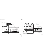
Connecting the Units
<ENGLISH>
Fig. 3
Power cable connection (1)
•
When using this unit at 40W
×
4ch.
•
When using this unit at 60W
×
4ch and the accessory fuse for the vehicle is 10A or more.
IP-BUS input
(Blue)
Multi-CD player
(sold separately)
Antenna jack
Refer to Fig. 5.
This product
15 cm
(5-7/8 in.)
Left
Right
+
≠
+
≠
+
≠
+
≠
Yellow/black
If you use a cellular telephone, connect it
via the Audio Mute lead on the cellular
telephone. If not, keep the Audio Mute
lead free of any connections.
Yellow
To separately sold power supply
wiring kit (RD-221).
Red
To separately sold power supply
wiring kit (RD-221).
Orange/white
To lighting switch terminal.
Black (ground)
To vehicle (metal) body.
Blue/white
To system control terminal of the power amp or
Auto-antenna relay control terminal (max. 300
mA 12 V DC).
Front speaker
Front speaker
With a 2 speaker system, do not connect
anything to the speaker leads that are not
connected to speakers.
Gray
Gray/black
Violet
Violet/black
White
White/black
Green
Green/black
IP-BUS cable
Fuse holder
Fuse holder
15 cm
(5-7/8 in.)
Jack for Wired Remote Control
Please see the Instruction Manual for the
Wired Remote Control (sold separately).
Black (ground)
To vehicle (metal) body.
For more detail, please refer to RD-221
owner’s manual.
Relay
Yellow
Power is always supplied
to this terminal.
Red
To electric terminal controlled
by ignition switch (12 V DC)
ON/OFF.
Red
Power is supplied to this
terminal when the ignition
key is in the ACC or ON
position.
Red
To electric terminal controlled
by ignition switch (12 V DC)
ON/OFF.
Rear speaker
or Subwoofer
Rear speaker
or Subwoofer
Fuse (1A)
Fuse
(20 A)
Power supply wiring kit “RD-221” (sold separately)
Fuse resistor
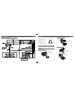
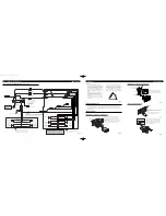
Fig. 4
Power cable connection (2)
•
When using this unit at 60W
×
4ch and the accessory fuse for the vehicle is less than 10A.
CRD3845A_inst 1/23/04 18:54 Page 5


