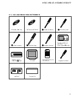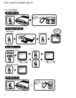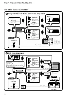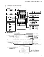
HTZ-7, HTZ-C7, HTZ-SW7, HTZ-ST7
102
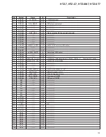
No.
Symbol
Name
I/O
Description
1
G1/A1
–––––
OUT
––––––––––
2
G0/A0
–––––
OUT
––––––––––
3
NC
–––––
––
––––––––––
4
PE0/INT0/EC0
–––––
IN
––––––––––
5
PE1/INT1/EC1
–––––
IN
––––––––––
6
PE2/INT2
–––––
IN
––––––––––
7
PE3/INT3/NM1
–––––
IN
––––––––––
8
PE4/RMC
SR_IN
IN
SR input
9
PE5
TEST_MODE
IN
Test mode when this port is “L” at the time of power ON
10
PE6/PWM
AUDIOSW_STAT3
OUT
AV switching strobe 3 (DIGITAL system)
11
PE7/TO/ADJ
AUDIOSW_STAT1
OUT
AV switching strobe (AUDIO system)
12
PC0/KR0
AUDIOSW_STAT2
OUT
AV switching strobe 2 (VIDEO system)
13
PC1/KR1
AUDIOSW_DATA
OUT
Function switching IC data
14
PC2/KR2
AUDIOSW_CLK
OUT
Function switching IC clock
15
PC3/KR3
–––––
OUT
––––––––––
16
PC4/KR4
SYSBUS_DI
IN
System bus data input [ for ID (priority) confirmation ]
17
PC5/KR5
SYSBUS_DO
IN/OUT
System bus data I/O (input except at the time of transmission)
18
PC6/KR6
SYSBUS_REQ
IN/OUT
System bus REQ I/O (input except at the time of transmission)
19
PC7/KR7
SYSBUS_CLK
OUT
System bus CLK output (always communication master)
20
PB0/CINT
DVD_XRDY
OUT
DVD-READY
21
PB1/CS0
DVD_LT1
IN
DVD latch
22
PB2/SCK0
DVD_XSCK
OUT
DVD serial data CLK
23
PB3/SI0
DVD_SI
IN
DVD serial data IN
24
PB4/SO0
DVD_SO
OUT
DVD serial data OUT
25
PB5/SCK1
DISP_CLK
OUT
Display communication transmission clock output
26
PB6/SI1
DISP_REQ_MD
OUT
Display communication REQ to MD
27
PB7/SO1
DISP_DATA
OUT
Display communication transmission data output
28
PI0
–––––
IN
––––––––––
29
PA0/AN0
KEY_IN
IN
AD input for main unit key input
30
PA1/AN1
SLEEP
IN
AD input for confirmation of microcomputer power supply 5.6 V DOWN (for backup)
31
PA2/AN2
FAN DET
IN
AD input for confirmation of heat dissipation fan operation
32
PA3/AN3
3.3V DET
IN
AD input for confirmation of DVD power supply 3.3 V DOWN (for sag correspondence)
33
PA4/AN4
MS1
IN
AD input for destination switching, 0: J/1: KU
34
PA5/AN5
AD_OVL
IN
AD input overload detection AD input
35
PA6/AN6
AV_5.6V
IN
AD input for confirmation of AV center 5.0 V power supply DOWN
36
PA7/AN7
XSTEREO/TUNED
IN
ADL for TUNER stereo reception OK/reception OK
37
PI1
–––––
––
GND
38
RST
–––––
––
Reset
39
EXTAL
–––––
––
Oscillator 16 MHz
40
XTAL
–––––
––
Oscillator 16 MHz
41
Vss
–––––
––
GND
42
PI2/TX
–––––
––
GND
43
PI3/TEX
–––––
––
GND
44
VDD
–––––
––
5V
45
Vfdp
–––––
––
GND
46
PD0/A55
TX_DI (OUT)
OUT
TUNER data output
47
PD1/A54
TX_CLOCK
OUT
TUNER clock output
48
PD2/A53
TX_CE
OUT
TUNER CE output
49
PD3/A52
TX_MUTE
OUT
TUNER mute output
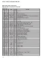
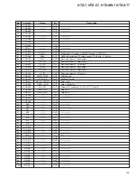
PDG251A (IC5501: MOTHER ASSY)
System Micro-computer (for AV center)
Pin Function
Содержание HTZ-7 VisionPlus
Страница 47: ...HTZ 7 HTZ C7 HTZ SW7 HTZ ST7 47 A B C D 5 6 7 8 5 6 7 8 S1 3 S 2 3 S 2 3 S 2 3 S 2 3 S 2 3 S 2 3 S 3 3 ...
Страница 49: ...HTZ 7 HTZ C7 HTZ SW7 HTZ ST7 49 A B C D 5 6 7 8 5 6 7 8 S2 3 S 1 3 S 1 3 S 3 3 S 3 3 ...
Страница 124: ...HTZ 7 HTZ C7 HTZ SW7 HTZ ST7 124 A B C D 1 2 3 4 1 2 3 4 7 4 2 SCHEMATIC DIAGRAM REFERENCE DOCUMENTATION ...

