49
HTP-071
5
6
7
8
5
6
7
8
A
B
C
D
E
F
8
. EACH SETTING AND ADJUSTMENT
8
.1 UPDATING OF THE FIRMWARE
[Purpose]
PC
UPDATE jig
GGF1642
Straight Cable
Adapter
JIG's side
RS-232C
Straight cable
Rear side
(MAI
N
microcomputer)
10P
10P
Refer to this section when updating the firmware of each microcomputer is required by the service information, etc.
[Necessary Tools and Connections]
1
MAIN microcomputer
• PC with a serial port
• RS-232C cable (9-pin to 9-pin, straight cable) (Marketing product)
• UPDATE jig: GGF1642 (Use FFC of GGF1642. (10P to 10P FFC))
• Firmware
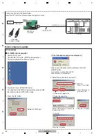
Connect as shown in the figure below.
Insert the FFC with its contact surface facing the
"
mark.
2
HDMI (SUB) and CEC microcomputer
<PC setting>
• PC with a USB port
• USB cable (Marketing product)
• UPDATE jig: GGF1646 (Use FFC of GGF1642. (10P to 10P FFC))
• Firmware
1. Thaw the upgrade program.zip.
Appear the below folderes and files.
Folder name: CDM20812
Folder name: EPConsole
Folder name:EPFlash_1_1_0_8
dot
N
etFx40_Full_setup.exe
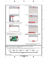
2. Install the driver.
Request the driver at the time of the conectting the Upgrade Jig and the PC with the USB cable.
Install the Driver (CDM20812).
3. Install .
N
ET Framework 3.0 service pack1.
To work EPFlash.exe (application for rewriting the HDMI u-co), request to be installed the .
N
ET Framework 3.0 service
pack1 on the PC.
For installation of .
N
ET Framework, Internet connection is required.
To confirm if .
N
ET Framework 3.0 Service Pack 1 has been installed on your PC or not, select Settings > Control Panel >
Add or Remove Programs. This confirmation method may be different, depending on the PC. Refer to the operation
manual of the PC you use on how to execute Add or Remove Programs.
4. Install .
N
ET Framwork 4.
To work EPConsole.exe , operate dot
N
ETFx40_Full_setup.exe and install .
N
ET Framework 4.
If
.
N
ET Framework 3.0 service pack1 doesn't install on the PC, you can not install .
N
ET Framework 4.
Please operate 4. after 3.
For installation of .
N
ET Framework, Internet connection is required.
10P to 10P FFC
Содержание HTP-071
Страница 9: ...9 HTP 071 5 6 7 8 5 6 7 8 A B C D E F ...
Страница 12: ...12 HTP 071 1 2 3 4 A B C D E F 1 2 3 4 4 2 OVERALL BLOCK DIAGRAM H FRONT ASSY A INPUT ASSY ...
Страница 13: ...13 HTP 071 5 6 7 8 5 6 7 8 A B C D E F ONT ASSY C MAIN ASSY C MAIN ASSY PUT ASSY B AMP ASSY F HP ASSY ...
Страница 56: ...56 HTP 071 1 2 3 4 A B C D E F 1 2 3 4 9 2 VSX 321 K P SECTION L N F G H DLPWXE only Cushion EVA Nut Nut ...
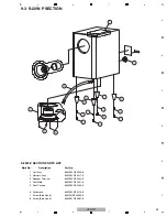
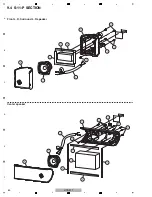
Страница 60: ...60 HTP 071 1 2 3 4 A B C D E F 1 2 3 4 9 4 S 11 P SECTION Center speaker Front L R Surround L R speaker ...
Страница 89: ...89 HTP 071 5 6 7 8 5 6 7 8 A B C D E F C SIDE B CP1 CP3 CP5 CN1 CN3 ...
Страница 90: ...90 HTP 071 1 2 3 4 A B C D E F 1 2 3 4 11 4 D MAIN ASSY D D D MAIN ASSY SIDE A E CN209 CN600 C CN5 CP104 ...
Страница 92: ...92 HTP 071 1 2 3 4 A B C D E F 1 2 3 4 D D D MAIN ASSY SIDE B CN601 CN603 IC104 IC603 IC604 IC605 IC606 ...
Страница 93: ...93 HTP 071 5 6 7 8 5 6 7 8 A B C D E F D SIDE B CN600 CP104 ...

