


BDP-HD1
73
5
6
7
8
5
6
7
8
C
D
F
A
B
E
7. GENERAL INFORMATION
7.1 DIAGNOSIS
7.1.1 SERVICE KEY INPUT
How to enter each check mode
• Each check mode described in this specification can be entered even during Normal Operation mode or for CA check,
by using the remote control unit for servicing.
• Key names enclosed in quotation marks (" ") are those on the remote control unit for servicing.
Specifications of the ESC code
• When the "ESC" key is pressed, ESCAPE mode is entered, and the next keypress will have a special meaning.
• If any key other than the ones indicated in the above table is the first one pressed after the "ESC" key, ESCAPE
mode is canceled.
• "ESC" key repeat is ignored, and ESCAPE mode is maintained.
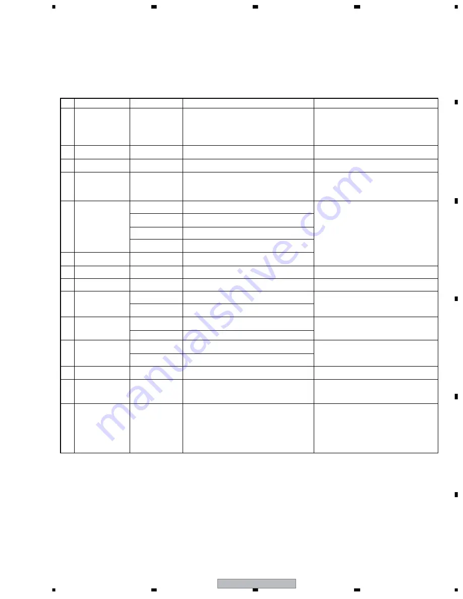
No.
Command Name
Key Input
Operation/Usage
Remarks
1
Settings at shipment
Press "ESC" then
"CLEAR."
For restoring the settings at shipment (The unit will not be turned
off.)
• Special condition for entering the mode: The unit must not
be in Playback mode.
• This check mode for settings at shipment (the unit will be
turned off) is the same as that entered by simultaneously
pressing the STOP and POWER keys on the main unit.
2
Error-Rate Measurement
mode 1 (with judgment)
Press "ESC" then
"SIDE B."
After automatic error-rate measuring, the results are displayed.
For details, refer to "7.1.3 How to measure the error rate."
3
Search mode
Press "ESC" then "+10."
Switching the numeric-key search from Chapter Search to Title
Search during playback of BD-ROM or DVD-Video discs.
4
Checking of the keys on
the main unit
Press "ESC" then
"SIDE A."
When a key on the main unit or the remote control unit is
pressed, the corresponding key code is displayed on the FL
display. If check results of pressing all the keys on the main unit
(the order of keypresses can be random) are "OK," all the
segments on the FL display light.
Keypresses can be in no particular order. After all the keys
on the main unit are pressed, all the segments on the FL
display light. Until that, the corresponding key code is
displayed when any key is pressed.
5
Switching of the settings
for OUTPUT FORMAT
Press "ESC" then "8."
The same operation as that when setting the Component output
to 480i.
The initial setting is Auto.
Press "ESC" then
"TV/LDP."
The same operation as that when setting the Component output
to 480p.
Press "ESC" then "1."
The same operation as that when setting the Component output
to 1080i.
Press "ESC" then "CX."
The same operation as that when setting the Component output
to 1080p.
6
Indications for Servicing
Press "ESC" then
"DISP."
For details on operations after key inputs, see the sheet "7.1.2
Screen indication for Servicing."
7
CPRM ID Registration
mode
Press "ESC" then
"STEREO."
Enter the specific ID number for the recorder, press the CPRM
and HDCP (and DTCP) keys, then enter the MAC address.
For details, see "6.2 CPRM ID number and Data setting."
8
Model Identification mode
Press "ESC" then
"DIG/ANA."
For confirmation of the destination and version number of the
model.
For production use.
9
On-Screen Display output
Press "ESC," "SEARCH,"
then "6," in that order.
For setting the On-Screen Display output to ON.
Use to stop the On-Screen Display output.
Press "ESC," "SEARCH,"
then "7," in that order.
For setting the On-Screen Display output to OFF.
10
Audio muting at the last
stage of output
Press "ESC" then "9."
For forcibly muting the audio output.
Press "ESC" then "0."
For forcibly canceling audio muting
11
Switching of the LED
display
Press "ESC" then
"REPEAT A."
All the segments on the LED display are lit.
Press "ESC" then
"REPEAT B."
All the segments on the LED display go dark.
12
Switching of the AUDIO
MULTI output
Press "ESC" then
"CHAP."
For setting the AUDIO MULTI output to All Channel Output
mode
14
4:3 Video out switch
Press "ESC", then
"FRM/TIM".
Switch TV ASPECT ratio in Video out to 4 : 3 (Standard).
The intitial setting is 16 : 9 (Widoscreen).
13
Error-Rate Measurement
mode 2 (for continuous
playback)
Press "ESC," "DISP,"
then "2," in that order.
After automatic error-rate measuring, the result is displayed as
an OSD.
• Special condition for entering the mode: The unit must be
in Playback mode.
• For details, see "7.1.3 How to measure the error rate."
Содержание Elite BDP-HD1
Страница 7: ...BDP HD1 7 5 6 7 8 5 6 7 8 C D F A B E ...
Страница 43: ...BDP HD1 43 5 6 7 8 5 6 7 8 C D F A B E CN205 CN204 CN203 CN201 CN202 G CN4001 F 7 7 CN6051 A 7 7 CN6002 A ...
Страница 72: ...BDP HD1 72 1 2 3 4 1 2 3 4 C D F A B E ...
Страница 78: ...BDP HD1 78 1 2 3 4 1 2 3 4 C D F A B E ...
Страница 89: ...BDP HD1 89 5 6 7 8 5 6 7 8 C D F A B E Pin Function ...
Страница 90: ...BDP HD1 90 1 2 3 4 1 2 3 4 C D F A B E ...
Страница 91: ...BDP HD1 91 5 6 7 8 5 6 7 8 C D F A B E ...
Страница 92: ...BDP HD1 92 1 2 3 4 1 2 3 4 C D F A B E ...
Страница 100: ...BDP HD1 100 1 2 3 4 1 2 3 4 C D F A B E ...
Страница 101: ...BDP HD1 101 5 6 7 8 5 6 7 8 C D F A B E HOST INTERFACE USB 2 0 Pin Function ...
Страница 103: ...BDP HD1 103 5 6 7 8 5 6 7 8 C D F A B E HOST INTERFACE PBI Pin Function HOST INTERFACE PBI Control Pin Function ...
Страница 104: ...BDP HD1 104 1 2 3 4 1 2 3 4 C D F A B E ...
Страница 108: ...BDP HD1 108 1 2 3 4 1 2 3 4 C D F A B E VIDEO PROCESSING SUBSYSTEM Digital Video Input 1 Pin Function ...
Страница 111: ...BDP HD1 111 5 6 7 8 5 6 7 8 C D F A B E VIDEO PROCESSING SUBSYSTEM HDMI Pin Function ...
Страница 113: ...BDP HD1 113 5 6 7 8 5 6 7 8 C D F A B E AUDIO PROCESSING SUBSYSTEM Audio Output Interface Pin Function ...
Страница 115: ...BDP HD1 115 5 6 7 8 5 6 7 8 C D F A B E SHARED PINS Uart Pin Function ...
Страница 116: ...BDP HD1 116 1 2 3 4 1 2 3 4 C D F A B E SHARED PINS GPIO Pin Function ...
Страница 117: ...BDP HD1 117 5 6 7 8 5 6 7 8 C D F A B E SHARED PINS Ethernet Pin Function MISCELLANEOUS PINS Miscellaneous Pin Function ...
Страница 118: ...BDP HD1 118 1 2 3 4 1 2 3 4 C D F A B E LISTING OF GROUND PINS VSS Ground Pin Function ...
Страница 119: ...BDP HD1 119 5 6 7 8 5 6 7 8 C D F A B E ...
Страница 120: ...BDP HD1 120 1 2 3 4 1 2 3 4 C D F A B E ...
Страница 121: ...BDP HD1 121 5 6 7 8 5 6 7 8 C D F A B E VOLT POWER RAIL 1 2V Power Rail VDD_1V2 Pin Function ...
Страница 123: ...BDP HD1 123 5 6 7 8 5 6 7 8 C D F A B E ...
Страница 124: ...BDP HD1 124 1 2 3 4 1 2 3 4 C D F A B E ...
Страница 125: ...BDP HD1 125 5 6 7 8 5 6 7 8 C D F A B E ...
Страница 126: ...BDP HD1 126 1 2 3 4 1 2 3 4 C D F A B E ...
Страница 127: ...BDP HD1 127 5 6 7 8 5 6 7 8 C D F A B E ...