background image

46

BDP-62FD

1

2

3

4

A

B

C

D

E

F

1

2

3

4

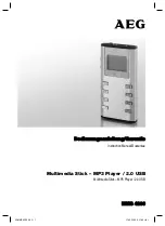
10.2  MAIN BOARD ASSY (2/11) : MT8555-DDR part2

A

2/11

B_RA1

B_RA0

B_RA13

B_RA3

B_RA7

B_RA6

B_RA4

B_RA2

B_RA5

B_RA8
B_RA9

B_RA11

B_RA10

B_RA12

B_DQS3#

B_DQS3

B_CLK0#

B_CLK0

B_DQS0
B_DQS0#

B_RRESET#

B_CAS#
B_RAS#
B_CS#
B_WE#
B_CKE

B_ODT

B
B

B

B

B

B

B

B

B

B

B

B

B

B

B

B
B
B
B

DDR_VREF

B_CLK1

B_CLK1#

B_DQS1#

B_DQS1

B

B_DQ10

B_DQ6

B_DQ11

B_DQ15

B_DQ2

B_DQ12

B_DQ5

B_DQ3

B_DQ1

B_DQ8

B_DQ0

B_DQ4

B_DQ9

B_DQ7

B_DQ13
B_DQ14

B_DQ26

B_DQ22

B_DQ27

B_DQ31

B_DQ18

B_DQ28

B_DQ21

B_DQ19

B_DQ17

B_DQ24

B_DQ16

B_DQ20

B_DQ25

B

B_DQ23

B_DQ29
B_DQ30

DDRIC_VREF

B

B

B_DQM1

B_DQM0

B_DQM2
B_DQM3

B_BA1

B_BA0

B_BA2

B_DQS2#

B_DQS2

1.5V

1.5V

1.5V

1.1V

1.1V

1.1V

1.1V

DDRIC_VREF

DDR_VREF

C245

0.1uF/25V/Y5V

C245

0.1uF/25V/Y5V

C253

0.1uF/16V/X7R

C253

0.1uF/16V/X7R

C259

0.1uF/16V/X7R

C259

0.1uF/16V/X7R

C208

0.1uF/16V/X7R

C208

0.1uF/16V/X7R

C216

0.1uF/16V/X7R

C216

0.1uF/16V/X7R

C84

1000pF/50V/X7R

C84

1000pF/50V/X7R

C251

0.1uF/16V/X7R

C251

0.1uF/16V/X7R

C262

0.1uF/16V/X7R

C262

0.1uF/16V/X7R

U7B

MT8555_0825_A

U7B

MT8555_0825_A

DVCC10_K

L10

DVCC10_K

W18

DVCC10_K

M9

DVCC10_K

W10

DVCC10_K

P11

DVCC10_K

V9

DVCC10_K

M19

DVCC10_K

N10

DVCC10_K

T11

DVCC10_K

P19

DVCC10_K

R10

DVCC10_K

V11

DVCC10_K

K11

DVCC10_K

L12

DVCC10_K

T19

DVCC10_K

K13

DVCC10_K

V13

DVCC10_K

K15

DVCC10_K

L14

DVCC10_K

U10

DVCC10_K

K17

DVCC10_K

V15

DVCC10_K

L16

DVCC10_K

K19

DVCC10_K

V17

DVCC10_K

V19

DVCC10_K

L18

DVCC10_K

N18

DVCC10_K

R18

DVCC10_K

U18

RDQ0_B

T25

RDQ1_B

T26

RDQ2_B

U26

RDQ3_B

U25

RDQ4_B

M26

RDQ5_B

M25

RDQ6_B

N28

RDQ7_B

N27

RDQ8_B

P23

RDQ9_B

T28

RDQ10_B

T27

RDQ11_B

T23

RDQ12_B

N26

RDQ13_B

P24

RDQ14_B

N23

RDQ15_B

N24

RDQ16_B

AF25

RDQ17_B

AG25

RDQ18_B

AH25

RDQ19_B

AH26

RDQ20_B

AA24

RDQ21_B

AB24

RDQ22_B

AA23

RDQ23_B

AB23

RDQ24_B

AD25

RDQ25_B

AE25

RDQ26_B

AH27

RDQ27_B

AH28

RDQ28_B

AC25

RDQ29_B

AD24

RDQ30_B

AC24

RDQ31_B

AC23

RDQM0_B

P25

RDQM1_B

R24

RDQM2_B

AD26

RDQM3_B

AE26

RDQS0_B

R27

RDQS0__B

R28

RDQS1_B

P28

RDQS1__B

P27

RDQS2_B

AG27

RDQS2__B

AG28

RDQS3_B

AF28

RDQS3__B

AF27

RODT_B

AD27

RCAS__B

AC26

RRAS__B

AD28

RCS__B

AB25

RWE__B

AE28

RCKE_B

V27

RRESET_B

Y26

RBA0_B

AB26

RBA1_B

T24

RBA2_B

W25

RA0_B

AE27

RA1_B

U24

RA2_B

W28

RA3_B

AA27

RA4_B

V24

RA5_B

AA28

RA6_B

W24

RA7_B

W27

RA8_B

Y24

RA9_B

W26

RA10_B

V28

RA11_B

V23

RA12_B

U23

RA13_B

Y25

RCLK0_B

L27

RCLK0__B

L28

RCLK1_B

AB27

RCLK1__B

AB28

RVREF_4

R23

RVREF_3

AA21

DVCC10_K

W12

DVCC10_K

W14

DVCC10_K

W16

C202

0.1uF/16V/X7R

C202

0.1uF/16V/X7R

R201

240

R201

240

C250

0.1uF/16V/X7R

C250

0.1uF/16V/X7R

C204

0.1uF/16V/X7R

C204

0.1uF/16V/X7R

C232

0.1uF/16V/X7R

C232

0.1uF/16V/X7R

C206

0.1uF/16V/X7R

C206

0.1uF/16V/X7R

C249

0.1uF/16V/X7R

C249

0.1uF/16V/X7R

C201

10P/50V/NPO

C201

10P/50V/NPO

C261

0.1uF/16V/X7R

C261

0.1uF/16V/X7R

C255

0.1uF/16V/X7R

C255

0.1uF/16V/X7R

C242

0.1uF/16V/X7R

C242

0.1uF/16V/X7R

C243

0.1uF/16V/X7R

C243

0.1uF/16V/X7R

C252

0.1uF/16V/X7R

C252

0.1uF/16V/X7R

C258

0.1uF/16V/X7R

C258

0.1uF/16V/X7R

C212

0.1uF/16V/X7R

C212

0.1uF/16V/X7R

C254

0.1uF/16V/X7R

C254

0.1uF/16V/X7R

C124

0.1uF/16V/X7R

C124

0.1uF/16V/X7R

C266

0.1uF/16V/X7R

C266

0.1uF/16V/X7R

C248

0.1uF/16V/X7R

C248

0.1uF/16V/X7R

C112

0.1uF/16V/X7R

C112

0.1uF/16V/X7R

C203

0.1uF/16V/X7R

C203

0.1uF/16V/X7R

C246

0.1uF/16V/X7R

C246

0.1uF/16V/X7R

C260

0.1uF/16V/X7R

C260

0.1uF/16V/X7R

C257

0.1uF/16V/X7R

C257

0.1uF/16V/X7R

C221

0.1uF/25V/Y5V

C221

0.1uF/25V/Y5V

C220

0.1uF/16V/X7R

C220

0.1uF/16V/X7R

C218

0.1uF/16V/X7R

C218

0.1uF/16V/X7R

C207

0.1uF/16V/X7R

C207

0.1uF/16V/X7R

C233

0.1uF/16V/X7R

C233

0.1uF/16V/X7R

C264

0.1uF/16V/X7R

C264

0.1uF/16V/X7R

C247

0.1uF/16V/X7R

C247

0.1uF/16V/X7R

C244

0.1uF/25V/Y5V

C244

0.1uF/25V/Y5V

C217

0.1uF/16V/X7R

C217

0.1uF/16V/X7R

C213

33P/50V/NPO

C213

33P/50V/NPO

C129

0.1uF/16V/X7R

C129

0.1uF/16V/X7R

C256

0.1uF/16V/X7R

C256

0.1uF/16V/X7R

Содержание Elite BDP-62FD

Страница 1: ...aan 1 9120 Melsele Belgium PIONEER ELECTRONICS ASIACENTRE PTE LTD 253 Alexandra Road 04 01 Singapore 159936 PIONEER CORPORATION 2012 2012 Printed in Japan BDP 62FD RRV4355 Blu ray 3DTM PLAYER BDP 62FD THIS MANUAL IS APPLICABLE TO THE FOLLOWING MODEL S AND TYPE S Model Type Power Requirement DVD Region No BD Region No Serial No Remarks BDP 62FD UCXE AC 110 V to 240 V 1 A UC UC NORTH AMERICA K FZV S...

Страница 2: ... 60 Hz outlet and turn the AC power switch on Any current measured must not exceed 0 5 mA ANY MEASUREMENTS NOT WITHIN THE LIMITS OUTLINED ABOVE ARE INDICATIVE OF A POTENTIAL SHOCK HAZARD AND MUST BE CORRECTED BEFORE RETURNING THE APPLIANCE TO THE CUSTOMER 2 PRODUCT SAFETY NOTICE Many electrical and mechanical parts in the appliance have special safety related characteristics These are often not ev...

Страница 3: ...t Location inside of the unit Printed on the Rear Panel Laser Pickup specifications and Laser characteristics For BD Wave length 398 412 nm Output Power Less than Class 1 For DVD Wave length 650 664 nm Output Power Less than Class 1 For CD Wave length 784 796 nm Output Power Less than Class 1 ...

Страница 4: ...39 8 2 FIRMWARE UPDATE 39 9 EXPLODED VIEWS AND PARTS LIST 41 9 1 PACKING SECTION 41 9 2 EXTERIOR SECTION 42 10 SCHEMATIC DIAGRAM 44 10 1 MAIN BOARD ASSY 1 11 MT8555 DDR part1 44 10 2 MAIN BOARD ASSY 2 11 MT8555 DDR part2 46 10 3 MAIN BOARD ASSY 3 11 MT8555 HDMI OUTPUT 48 10 4 MAIN BOARD ASSY 4 11 MT8555 FLASH 50 10 5 MAIN BOARD ASSY 5 11 MT8555 VFD SPDIF OUTPUT 52 10 6 MAIN BOARD ASSY 6 11 MT8555 ...

Страница 5: ...ly 40 ºC Therefore for lead free soldering the tip temperature of a soldering iron must be set to around 373 ºC in general although the temperature depends on the heat capacity of the PC board on which reworking is required and the weight of the tip of the soldering iron Do NOT use a soldering iron whose tip temperature cannot be controlled Compared with eutectic solders lead free solders have hig...

Страница 6: ... H x 915 16 in D 435 mm W x 90 mm H x 252 mm D Tolerable operating temperature 41 F to 95 F 5 C to 35 C Tolerable operating humidity 5 to 85 no condensation Output terminals HDMI 2 set 19 pin 5 V 250 mA Digital audio outputs Coaxial 1 set RCA jacks LAN 1 set Ethernet jack 10BASE T 100BASE TX USB 2 set Type A The specifications and design of this product are subject to change without notice This it...

Страница 7: ...S CD DATA DISC1 BD2 BD ROM BD R BD RE DVD DVD ROM DVD R2 3 4 5 6 DVD RW3 7 5 6 DVD R2 3 DVD RW3 CD CD DA Audio CD 8 CD R3 CD RW3 CD ROM 1 Discs on which video image or audio files are recorded This player does not support multisession discs or multiborder recording 2 Including dual layered discs 3 Finalize them before playing them on this player 4 DVD R for Authoring discs 3 95 and 4 7 GB cannot b...

Страница 8: ...h these audio formats using an HDMI cable After loading a BD containing sound in one of these audio formats select the audio format on the menu screen Some discs cannot be played even if one of the logo marks on the previous page is indicated To play 8 cm discs set the disc in the 8 cm disc depression in the center of the disc tray No adapter is necessary 8 cm BD ROMs cannot be played Manufactured...

Страница 9: ...ROM or DVD Video discs are assigned region numbers according to the region in which they are sold This player s region numbers are BD ROM A DVD Video 1 Discs not including these numbers cannot be played Discs playable on this player are as shown below BDs A including A and ALL DVDs 1 including 1 and ALL A DualDisc is a two sided disc one side of which contains DVD content video audio etc while the...

Страница 10: ... Corporation or its subsidiaries and are used under license This DivX Certified device must be registered in order to play DivX Video on Demand VOD content First generate the DivX VOD registration code for your device and submit it during the registration process Important DivX VOD content is protected by a DivX DRM Digital Rights Management system that restricts playback to registered DivX Certif...

Страница 11: ...te Up to 192 kbps Audio type WMA version 9 LPCM wav Sampling frequencies Up to 192 kHz Quantization bitrate 16 bit Channel 2ch FLAC flac Sampling frequencies Up to 192 kHz Quantization bitrate 16 bit 24 bit Channel 2ch JPEG jpg jpeg Maximum resolution 4 000 x 3 000 pixels DivX avi divx mkv Supported versions Through DivX PLUS HD Maximum resolution Up to 1 920 x 1 080 DivX PLUS HD Up to 1 280 x 720...

Страница 12: ...or the operation check The customer complain must not be reappeared Video audio and operations must be normal Play back a CD track search Audio and operations must be normal Play back a DVD Menu operation Title chapter search Video audio and operations must be normal Play back a BD Menu operation Title chapter search Video audio and operations must be normal Check the appearance of the product No ...

Страница 13: ...ARD ASSY FRONT BOARD ASSY SWITCH BOARD ASSY MAIN BOARD ASSY A D B Loader ASSY C Mark No Description Part No LIST OF ASSEMBLIES 1 MAIN BOARD ASSY 08 BDP450 MA2 U 1 FRONT BOARD ASSY 08 BDP450 FV1 1 SWITCH BOARD ASSY 08 BDLX55 SW0 TL 1 POWER BOARD ASSY 08 BDP450 PW2 1 Loader ASSY 08 LTCA19 LD0 DVD Test Disc DVD Video BD ROM Test Disc Name Jig No Remarks Check of DVD Video Check of BD ROM GGV1025 GGV1...

Страница 14: ...IN 1 0 8 1 1 4 XP5 4PIN 2 0 XP6 USB_1 4PIN 2 0 1 4 P503 CON2 RS232 4PIN 2 0 1 12 XP16 1 10 Ethernet P3 PQLS HDMI 1 16_B P2 USB2 Aud F25 G27 GPIO7 POWER_K 12V_D VCC GND VDATA GND POWER_K VCLK OPEN_K 24V_D TRAYIN GND LOAD LOAD A A B B U V W C VSTB IR LED 27M C F25 232 TX G27 232 RX PWM LOADER ASSY 08 LTCA19 LD0 SWITCH BOARD ASSY 08 BDLX55 SW0 TL C FRONT BOARD AS 08 BDP450 FV1 B A MAIN BOARD ASSY 08 ...

Страница 15: ...DSD SPDIF LDO LDO 1 8V 1 0V 512Mbit DDR2 CEC SWITCH 74L157 2D 3D 20_BIT 444 Y Cb Cr PCM DSD SWITCH UPD78F1156A uCOM MCU I2C 12V GND 5V GND 5V 12V D VCC GND VDATA VCLK 24V VSTB IR CEC_1 CEC CEC_CONT GND BOARD ASSY P450 FV1 POWER BOARD ASSY 08 BDP450 PW2 D Therefore when replacing be sure to use parts of identical designation When ordering service parts be sure to refer to EXPLODED VIEWS and PARTS L...

Страница 16: ...3 L502 3 3u L503 3 3u L1 2 2u 2 2u DDRIC_VREF R40 0 U42 SII9136 U14 88DE2750 U24 NT5TU32M16CG 25C DDR2 DCDC Conv DCDC Conv U15 G5725 U16 G5725 1 8V 1 0V 3V3_KYOTO_G2 3 3V 1 2V_SII9136 3 3V U103 G2992 VREF 100 FB12 FB10 FB27 OPWRSB EN FB26 FB25 FB23 FB28 FB22 L3 FB19 FB30 R25 0 FB14 FB20 1V8_KYOTO_G2_DDR2 1V_KYOTO_G2 FB21 D21 SWITCH U32 TS5A315 2HDMI CEC SWITCHER 0 0 R173 R174 DDR2 VTT VTT 3V3_KYOT...

Страница 17: ...P7 28 37 R210 VCC_PDIC VCC_HFM R216 0 to Pickup U12 2 2 U135 PT6302 FL Driver FL_AC CIRCUIT IR1 IRM VFD135 FL TUBE 6 7 10 R23 R24 1k 5V ZD1 R20 100 4 U18 G556B1 USB_VCC2 P503 USB TERMINAL P221 USB TERMINAL XS135 ZD3 XS221 24V_D 12V_D VCC VCC_USB ZD1 Q150 U42 SII9136 1 2V_SII9136 0 J3 HDMI TERMINAL F2 0 VCC R1376 FB713 D21 SWITCH U32 TS5A315 2HDMI CEC SWITCHER FB29 U43 UPD78F1166A FB24 3 3V_STBY U1...

Страница 18: ...FRONT BOARD ASSY If there is no problem please replace the MAIN BOARD ASSY Check whether the voltage of XS135 pin6 on the FRONT BOARD ASSY is 5 V and X135 pin7 is 12 V When the remote controller and the Main Unit power button cannot turn on the power When there is no change Replace the FRONT BOARD ASSY Replace the MAIN BOARD ASSY When only the Main Unit power button is not active to turn on the po...

Страница 19: ...l Check the connect line is OK Correct connection Replace SW1 SW2 and SW3 If still same situation replace the FRONT BOARD ASSY Yes No No Check the FRONT BOARD ASSY signals VSTB VCLK VD XS135 pin3 4 5 Check whether the circuit connected to SW1 SW2 and SW3 Check if Q206 and U12 are soldering normally on the MAIN BOARD ASSY Resolder Q206 and U12 If still same situation replace the MAIN BOARD ASSY Yes...

Страница 20: ...es No Yes Remote control does not work No Replace the battery for remote controller Check whether the remote controller s battery is exhausted or not Check the IR1 HT68F50 power supply is OK IR1 pin3 is about 3V Check the VCC line net on the FRONT BOARD ASSY Replace IR1 Yes ...

Страница 21: ... running is normal Fix the connection the 45 pin cable or 8 pin cable No Yes Check if U4 pin2 voltage is normal about 9V No No Check R203 and R209 are normal the voltage between two resistance is 1 5V Yes Yes Resolder R1376 If still same situation replace the MAIN BOARD ASSY Resolder R203 or R209 If still same situation replace the MAIN BOARD ASSY No No Check if R1376 is soldering normally on the ...

Страница 22: ...nect to network Yes Check if R579 R580 R581 and R582 are soldering normally on the MAIN BOARD ASSY Check if U553 is soldering normally on the MAIN BOARD ASSY No Yes Yes Resolder U553 If still same situation replace the MAIN BOARD ASSY Resolder all resistors If still same situation replace the MAIN BOARD ASSY Resolder P2 If still same situation replace the MAIN BOARD ASSY ...

Страница 23: ...ode Check if HDMI Mode is on Separate Mode or Pure Audio Mode Resolder all resistors If still same situation replace the MAIN BOARD ASSY Check if HDMI line is connected from the loader No Connected HDMI line from the loader to the MAIN BOARD ASSY Yes Yes Replace the MAIN BOARD ASSY Check if F2 R66 R67 and R74 are soldering normally on the MAIN BOARD ASSY ...

Страница 24: ...de Check if HDMI Mode is on Dual Mode or Separate Mode Check if HDMI line is connected from the loader No Connected HDMI line from the loader to the MAIN BOARD ASSY Yes No Yes Replace the MAIN BOARD ASSY Check if F1 R122 R123 and R176 are soldering normally on the MAIN BOARD ASSY Resolder all parts If still same situation replace the MAIN BOARD ASSY ...

Страница 25: ...ot appear slowly press the number keys with a 1 second interval 1 Enter FA mode Implemented when exchanging the Loader and MAIN BOARD ASSY Refer to FA Mode for details 2 Save FE log to USB For Design and Development purposes and cannot be used for Service 3 Save FA result to USB For Design and Development purposes and cannot be used for Service 4 Laser Check Verifies laser diode Refer to Laser Che...

Страница 26: ...mplement FA mode as in the following instructions 1 Select 1 Enter FA mode with the up and down key on the remote control on the Service Mode screen and press the ENTER key Window below will appear 2 The tray will open automatically so insert GGV1368 and close the tray manually push the tray in 3 Adjustments will initiate and when they are properly completed the tray will re open and Insert Disc B...

Страница 27: ...PASS will appear and if any of them goes over NG will appear 1 Select 4 Laser Check with the key from the Service Mode screen and press the ENTER key perform without disc in tray BD Measurement values The hexadecimal single digit will not be displayed in Meas Therefore in the above example Measurement values of up to 0x49 are considered OK and 0x50 are considered NG 0x is simply to express the hex...

Страница 28: ...re related to discs implment on the type of disc which has been pointed out If it is the disc on which the indications occurred possibility of reoccurrence is higher Content of test Measures the Jitter or the Block Error Rate BLER of the disc inserted Only Pass or NG will be displayed not Measurement values All of CD DVD and BD can be judged Instructions 1 Select 7 Enter SP Mode with the key from ...

Страница 29: ...d up until 9C3D 39997 in decimal however later it is expressed as 32 and is finished Note 3 DVD and BD disc can be checked with Single Layer SL disc only If they are checked with Dual Layer DL disc an Error is generated Note 4 Set Auto Power OFF function in the setting of main unit to OFF If the function is executed in any setting status the power supply is turned OFF at the time Error code Error ...

Страница 30: ...e Service Mode The pick up position does not return even in this status The measurement at the place is available 2 Select 8 PDXY Check with the key from the Service Mode screen and press the ENTER key 3 After the measurement is started and completed the measurement value is displayed If the value is within the reference value Pass is displayed Effective indications Defect related to playback bloc...

Страница 31: ...cribed here are common Top Cover ASSY 1 Tray Door Section 1 1 Top Cover ASSY 1 Remove the six screws 63 B30060 3H3 TL 2 Take out the Top Cover ASSY upward while spreading Rear Side Piece 1 2 Tray Door ASSY 1 Press the STANDBY ON button to turn on the power 2 Press the OPEN CLOSE button to open the Tray 3 Remove upward the Tray Door ASSY 4 Press the OPEN CLOSE button to close the Tray 5 Press the S...

Страница 32: ...D ASSY 3 3 How to open the Tray when the power cannot be turned on When the Tray cannot be opened because the power cannot be turned on it can be opened using the Emergency Disc Ejection Rod GGF1529 A long thin rod about 1 mm in diameter can be used in place of the rod Emergency Disc Ejection Rod is inserted from Notch of the Stand of Loader ASSY and slide the Loading Rack in the direction of blue...

Страница 33: ...on assembling Insert the two projections on the Loader ASSY front side in the projections of the Front Panel ASSY 3 MAIN BOARD ASSY Remove the Top Cover ASSY Refer to the 1 1 Top Cover ASSY 1 Remove the two screws 64 B30060 304 TL 2 Remove the screw 63 B30080 BF3 TL 3 Disconnect the connector 4 Remove the four screws 63 B30070 3H4 TL ...

Страница 34: ...der ASSY and disconnect the five connectors 6 Remove the six screws 63 B30060 3H4 TL 7 Slide the MAIN BOARD ASSY to the front side and then remove it Note Take note that MAIN BOARD ASSY is attached to the Chassis with the Sheet 4 Front Panel Section Remove the Tray Door ASSY Refer to the 1 Tray Door Section 1 Remove the screw 63 B30060 3H4 TL 2 Remove the screw 63 B30080 BF3 TL 3 Remove the Acetat...

Страница 35: ...35 BDP 62FD 5 6 7 8 5 6 7 8 A B C D E F 5 5 5 5 Bottom view Front Panel ASSY 5 Unhook the four hooks of the Front Panel ASSY and remove the Front Panel Section ...

Страница 36: ...ook each two places of the Hooks of right and left and remove the Top Cover Clean the pickup lenses when it is stained using following cleaning materials Cleaning liquid GEM1004 Cleaning paper GED 008 Caution The pickup for Blu ray is a high precision component therefore clean the lens with enough care so as not to cause a misalignment in the optical axis Cleaning the Pickup Lenses ...

Страница 37: ...SSY MAIN BOARD ASSY Loader ASSY XP10 XP7 Contact Side Non Contact Side 1 Styling of cables Notes on assembling Caution 1 When you attach each unit make a styling and connection of cables as shown in the photo Caution 2 Nothing should be connected to the connector parts surrounded by red line Be careful not to connect cable by mistake ...

Страница 38: ...38 BDP 62FD 1 2 3 4 A B C D E F 1 2 3 4 Bottom view Insulator 2 Direction of Insulator Align the mark at under surface of the Insulator 56 BD44E1 0HA with the direction of photo ...

Страница 39: ...h of firmware update the file name and the specification of update are constantly changing The following are the steps of update 1 Before upgrade please check the current version of firmtware installed in this machine You can press HomeMenu button to enter the menu after that press button to display Home Menu Initial Setup Options System Information then you can see the information of current firm...

Страница 40: ...40 BDP 62FD 1 2 3 4 A B C D E F 1 2 3 4 ...

Страница 41: ...amount of lubricants or glue follow the instructions in this manual In the case of no amount instructions apply as you think it appropriate Mark No Description Part No 1 AC Power Cord 51 BC0150 0LSA9 TL 2 Operating Instructions En Fr Es 72 BDP450 USAB1 3 Polyethylene Bag 74 056045 50HB4 4 Packing Case 76 106630 0ATD7 NSP 5 License Notice ARC8136 6 Remote Control Unit RC 2921 06 RC2921 A000 TL 7 Fr...

Страница 42: ...42 BDP 62FD 1 2 3 4 A B C D E F 1 2 3 4 9 2 EXTERIOR SECTION CONTACT SIDE NON CONTACT SIDE A A A A B B A C B D Acetate Tape Acetate Tape Double side tape ...

Страница 43: ...le 46 FH018F 04MA TL 12 45 pin 180 mm Cable 46 KF018C 45BU 13 Top Cover ASSY 08 BDP450 TA0 14 Tray Door ASSY 08 BDP450 DA1 15 Front Panel ASSY 08 BDP450 FA2 16 Rubber Pad 54 106480 000 TL 17 Insulator 56 BD44E1 0HA 18 Rubber Pad 59 111850 000 19 Sheet 28 x 28 x 2 0 59 997910 000 TL 20 Ground Plate 67 BD14Q1 0B0 TL 21 Rear Panel 67 BD45B1 1E0B1 22 S T Screw B 2 6 x 6 BF 63 B26060 BF4 TL 23 S T Scre...

Страница 44: ...12_MEMPLL AE23 AVSS12_MEMPLL AD23 TP_MEMPLL AE24 TN_MEMPLL AF24 DGND AA26 DGND AA12 DGND L11 DGND M10 DGND K10 DGND N11 DGND P10 DGND L13 DGND R11 DGND L15 DGND T10 DGND U11 DGND M12 DGND M13 DGND M14 DGND M15 DGND M17 DGND AA14 DGND V10 DGND N12 DGND N13 DGND N14 DGND N15 DGND N16 DGND W11 DGND P12 DGND P13 DGND P14 DGND P15 DGND P17 DGND K12 DGND R12 DGND R13 DGND R14 DGND R15 DGND R16 DGND AA16...

Страница 45: ..._8 H9 DQ4 H3 VSSQ_8 G9 DQ3 F8 DQ2 F2 BA2 M3 DQ5 H8 VDD_5 N1 VREFDQ H1 VSS_2 E1 VSS_5 J8 CK J7 VDD_2 G7 CKE K9 WE L3 RAS J3 CK K7 ODT K1 RESET T2 BA0 M2 BA1 N8 CAS K3 CS L2 A10 AP L7 A1 P7 A2 P3 A0 N3 VDD_3 K2 VSS_3 G8 A3 N2 A5 P2 A6 R8 A4 P8 A7 R2 A9 R3 A11 R7 A8 T8 VSS_4 J2 VDD_4 K8 A12 BC N7 NC_3 L9 ZQ L8 NC_2 L1 VREFCA M8 NC_4 M7 A13 T3 NC_6 T7 VSS_6 M1 VSS_7 M9 VSS_8 P1 VSS_9 P9 VSS_10 T1 VSS_...

Страница 46: ...RDQ27_B AH28 RDQ28_B AC25 RDQ29_B AD24 RDQ30_B AC24 RDQ31_B AC23 RDQM0_B P25 RDQM1_B R24 RDQM2_B AD26 RDQM3_B AE26 RDQS0_B R27 RDQS0__B R28 RDQS1_B P28 RDQS1__B P27 RDQS2_B AG27 RDQS2__B AG28 RDQS3_B AF28 RDQS3__B AF27 RODT_B AD27 RCAS__B AC26 RRAS__B AD28 RCS__B AB25 RWE__B AE28 RCKE_B V27 RRESET_B Y26 RBA0_B AB26 RBA1_B T24 RBA2_B W25 RA0_B AE27 RA1_B U24 RA2_B W28 RA3_B AA27 RA4_B V24 RA5_B AA2...

Страница 47: ...VSSQ_0 B1 UDQS B7 VDDQ_0 A1 DQ14 B8 VSSQ_1 B9 UDM D3 UDQS C7 VSSQ_2 D1 DQ15 A3 VDDQ_1 A8 DQ9 C3 VDDQ_2 C1 VDDQ_3 C9 DQ8 D7 VDDQ_4 D2 DQ12 A7 VSSQ_3 D8 DQ11 C2 DQ10 C8 VSSQ_4 E2 DQ13 A2 VDD_1 D9 NC_1 J9 VSS_1 B3 VSSQ_5 E8 LDQS G3 VDDQ_5 E9 DQ6 G2 VSSQ_6 F9 LDM E7 LDQS F3 VSSQ_7 G1 DQ7 H7 VDDQ_6 F1 DQ1 F7 VDDQ_7 H2 DQ0 E3 VDDQ_8 H9 DQ4 H3 VSSQ_8 G9 DQ3 F8 DQ2 F2 BA2 M3 DQ5 H8 VDD_5 N1 VREFDQ H1 VSS_...

Страница 48: ..._APLL G14 AVDD12_27MPLL E15 AVSS12_27MPLL E14 TP_PLLG C14 TN_PLLG D14 NS_XTALI A13 NS_XTALO B13 AOMCLK C12 AOBCK A12 AOLRCK B12 AOSDATA0 C11 AOSDATA1 D11 AOSDATA2 D12 AOSDATA3 E10 AOSDATA4 F10 SPDIF E13 MCIN E12 AMUTE D10 VDACX_OUT C19 VDACR_OUT C18 VDACG_OUT A19 VDACB_OUT B19 FS D18 AVDD12_HDMI_TX E16 AVSS12_HDMI_TX G16 AVDD12_HDMI_TX D16 AVSS12_HDMI_TX F16 AVDD33_HDMI_TX C17 AVSS33_HDMI_TX E17 A...

Страница 49: ...XO 27M Y4 VCXO 27M Vc 1 GND 2 OUT 3 VDD 4 C411 33pF 50V X7R C411 33pF 50V X7R R74 33 R74 33 R401 100K R401 100K C343 10uF 10V C343 10uF 10V R355 10K R355 10K R15 0 R15 0 C342 33pF 50V NP0 C342 33pF 50V NP0 R398 20K 1 R398 20K 1 D313 LVSL10180Z020 18V 2pF D313 LVSL10180Z020 18V 2pF 2 1 C340 10pF 50V NP0 C340 10pF 50V NP0 L861 TDK ACM2012H 900 2P 0 DLW21SN900SQ2L 2 L861 TDK ACM2012H 900 2P 0 DLW21SN...

Страница 50: ... X7R C421 4 7uF 10V Y5V C421 4 7uF 10V Y5V C422 0 1uF 16V X7R C422 0 1uF 16V X7R C935 0 1uF 25V Y5V C935 0 1uF 25V Y5V C86 0 1uF 16V X7R C86 0 1uF 16V X7R C93 0 1uF 16V C93 0 1uF 16V TP409 TP409 C92 0 1uF 16V X7R C92 0 1uF 16V X7R R435 24K 1 R435 24K 1 C550 NC 100pF 2000V C550 NC 100pF 2000V R581 75 1 R581 75 1 R582 75 1 R582 75 1 C424 0 1uF 16V X7R C424 0 1uF 16V X7R U553 LFE8634 U553 LFE8634 RD ...

Страница 51: ...10K C99 0 1uF 16V X7R C99 0 1uF 16V X7R TP73 TP73 X7R X7R R408 4 7K R408 4 7K TP78 TP78 O O C404 0 1uF 16V X7R C404 0 1uF 16V X7R C353 NC C353 NC CB403 0 1UF 16V Y5V CB403 0 1UF 16V Y5V R551 10K R551 10K TP75 TP75 C89 0 1uF 16V X7R C89 0 1uF 16V X7R U401 NAND 256MB U401 NAND 256MB VCC 12 NC 11 CE2 10 CE1 9 RE 8 R B1 7 R B2 6 NC 5 NC 23 NC 4 NC 3 NC 2 VSS 13 NC 14 NC 15 ALE 17 WE 18 WP 19 NC 20 NC ...

Страница 52: ...VDINVSYNC F27 VDINCLK F28 VDD12_HDMI_RX D8 C657 0 1uF 16V X7R C657 0 1uF 16V X7R LCDRD ETTXEN 0 Normal mode LCDRD ETTXEN 1 RST by SVO mode LCDRD ETTXEN 2 Monitor mode LCDRD ETTXEN 3 Test scan mode AO2SDATA2 Play_K SPDIF2 POWER_K OPEN_K VCXO_1 65V_CTL DVCC33_IO_STB AVDD33_LDO LCDRD ETTXEN_VOUTD14 AO2BCK SD2 DL1 AO2MCLK OPWRSB IR VSTB VCLK VDATA UATXD UARXD AVDD33_LDO AO2SDATA3 LCDRD ETTXEN_VOUTD14 ...

Страница 53: ... 27pF 50V NP0 R89 0 R89 0 12V_D 12V_D R684 KLN221 R684 KLN221 C214 27pF 50V NP0 C214 27pF 50V NP0 C515 0 1uF 16V X7R C515 0 1uF 16V X7R OPEN_K OPEN_K R90 33 R90 33 C209 27pF 50V NP0 C209 27pF 50V NP0 C211 27pF 50V NP0 NC C211 27pF 50V NP0 NC VCLK1 VCLK1 VSTB1 VSTB1 R149 100 R149 100 R128 NC 10K R128 NC 10K C514 0 1uF 50V X7R C514 0 1uF 50V X7R R81 10K R81 10K R101 33 R101 33 PLAY_K PLAY_K R87 10K ...

Страница 54: ...FM C721 0 1uF 25V Y5V C721 0 1uF 25V Y5V R712 0 R712 0 C229 0 1uF 16V X7R C229 0 1uF 16V X7R TPIC_TR TPIC_TR TPIC_FR TPIC_FR NC02 0603 R NC02 0603 R DVD_VR DVD_VR C235 10uF 10V Y5V C235 10uF 10V Y5V AUX1 AUX1 U7F MT8555_0825_A BGA606 0 8 MT8555 U7F MT8555_0825_A BGA606 0 8 MT8555 V14 K6 FVREF H6 HAVC K5 TRINA G3 TRINB H4 TRINC H3 TRIND H5 INA G2 INB G1 INC H2 IND H1 INE K3 INF K4 ING J4 INH J3 FOI...

Страница 55: ...PIC_FG 11 TPIC_VWDC2O 11 TPIC_DVD_LD 11 R209 1K R209 1K C875 10uF 10V Y5V C875 10uF 10V Y5V HAVC HAVC R703 10K R703 10K FVREF FVREF C272 100pF 25V Y5V C272 100pF 25V Y5V C239 0 1uF 25V Y5V C239 0 1uF 25V Y5V R706 NC 10K R706 NC 10K C224 0 1uF 16V X7R C224 0 1uF 16V X7R C269 10uF 10V Y5V C269 10uF 10V Y5V FPDOCD FPDOCD TM68 TM68 R228 0 R228 0 GAINSW2 GAINSW2 R1031 0 R1031 0 VDAC0 VDAC0 R232 0 R232 ...

Страница 56: ...U TPIC_V TPIC_W TPIC_FR TPIC_FR TPIC_TR TPIC_TR TPIC_TL TPIC_TL TPIC_A TPIC_A TPIC_B TPIC_B TPIC_CO_B TPIC_FG TPIC_BD_LD TPIC_DVD_LD TPIC_MUTE1 PULL_CTL VLDDIN TPIC_GIO2 TPIC_TYPWM TPIC_FMO1 TPIC_FMO2 A9P5V TPIC_VWDC2O TPIC_LOAD TPIC_LOAD A9P5V VCC_D M12V_T 12V_D M M12V_T M MVCC_T MVCC_T M M12V_T MVCC_T M M MV A3 3VM A3 3VM A3 3V M 12V_D VCC_OPU GND GND M AVCC M FB16 300 2A FB16 300 2A C760 0 1uF ...

Страница 57: ...DQ3 H3 DQ2 H7 DQ1 G2 DQ0 G8 UDM B3 LDM F3 UDQS B7 UDQS NU A8 LDQS F7 LDQS NU E8 VSS5 P9 VSS4 N1 VSS3 J3 VSS2 E3 VSS1 A3 VSSQ10 H8 VSSQ9 H2 VSSQ8 F8 VSSQ7 F2 VSSQ6 E7 VSSQ5 D8 VSSQ4 D2 VSSQ3 B8 VSSQ2 B2 VSSQ1 A7 VSSDL J7 RFU A14 R3 RFU A15 R7 50G4 remodify 2011 12 12 remodify 2011 12 12 TPIC_CO_B TPIC_CO_A TPIC_CO_A TPIC_COMMON TPIC_U TPIC_V TPIC_W TPIC_FR TPIC_FR TPIC_TR TPIC_TR TPIC_TL TPIC_TL TP...

Страница 58: ... 10V Y5V C28 22uF 10V Y5V C58 0 1uF 16V X7R C58 0 1uF 16V X7R RN142 33 4 RN142 33 4 1 2 3 4 6 5 8 7 C24 22uF 10V Y5V C24 22uF 10V Y5V C67 0 1uF 16V X7R C67 0 1uF 16V X7R C79 0 1uF 16V X7R C79 0 1uF 16V X7R C431 0 1UF 50V NP0 C431 0 1UF 50V NP0 C138 0 1uF 16V X7R C138 0 1uF 16V X7R C158 0 1uF 16V X7R C158 0 1uF 16V X7R FB10 FB500 0 5A FB10 FB500 0 5A R64 4 7K R64 4 7K C442 10pF 50V NP0 C442 10pF 50...

Страница 59: ...VDD K12 DVDD L12 DVDD M9 DVDD M10 DVDD M11 DVDD M12 DVDD M14 DVDD R15 DVDD R16 DVDD T15 DVDD T16 DVDD P14 DVDD N13 VSS A1 VSS B2 VSS C3 VSS D4 DVDD D8 VSS E6 VSS E5 VSS E7 DVDD E8 VSS E14 VSS F6 VSS F7 VSS F8 VSS F9 VSS F10 VSS F11 VSS G6 VSS G7 VSS G8 VSS G9 VSS G10 VSS G11 VSS H6 VSS H7 VSS H8 VSS H9 VSS H10 VSS H11 VSS H15 VSS J6 VSS J7 VSS J8 VSS J9 VSS J10 VSS J11 VSS K6 VSS K7 VSS K8 VSS K9 ...

Страница 60: ...20 95 D21 94 D22 93 D23 92 D24 90 D25 89 D26 87 D27 86 D28 85 D29 84 D30 83 D31 82 D32 81 D33 80 D34 79 D35 78 DE 25 HSYNC 24 VSYNC 23 IDCK 22 SPDIF_IN DL2 29 MCLK 36 SCK 35 WS DR0 34 SD3 DR2 30 SD2 DL1 31 SD1 DR1 32 SD0 DL0 33 EXT_SWG 52 TX0_N 57 TX0_P 58 TX1_N 59 TX1_P 60 TX2_N 62 TX2_P 63 TXC_P 55 TXC_N 54 DSCL 42 DSDA 41 HPD 76 IRQ 46 CSCL 45 CSDA 44 CI2CA 43 TESTMODE 48 DL3 27 DR3 28 SPDIF_OU...

Страница 61: ...20 18V 2pF 2 1 R36 0 R36 0 R116 4 7K R116 4 7K R127 1 8K R127 1 8K C341 10uF 10V Y5V C341 10uF 10V Y5V R122 33 R122 33 D315 LVSL10180Z020 18V 2pF D315 LVSL10180Z020 18V 2pF 2 1 L866 TDK ACM2012H 900 2P 0 DLW21SN900SQ2L 2 L866 TDK ACM2012H 900 2P 0 DLW21SN900SQ2L 2 1 3 2 4 L867 TDK ACM2012H 900 2P 0 DLW21SN900SQ2L 2 L867 TDK ACM2012H 900 2P 0 DLW21SN900SQ2L 2 1 3 2 4 C300 10pF 50V NP0 C300 10pF 50V...

Страница 62: ...V C412 0 1uF 25V R360 33 OHM R360 33 OHM R R R329 4 7K R329 4 7K Q7 NPN_3DG3904M Q7 NPN_3DG3904M R345 0 R345 0 Q10 NPN_3DG3904M Q10 NPN_3DG3904M R366 0 R366 0 R357 4 7K R357 4 7K R367 0 R367 0 C495 33P 50V NPO C495 33P 50V NPO R351 10K R351 10K R359 100R R359 100R FB24 FB10 2A ELN100 FB24 FB10 2A ELN100 R368 0 R368 0 U32 TS5A3157 U32 TS5A3157 NO 1 GND 2 NC 3 COM 4 V 5 IN 6 R332 0R R332 0R R346 0 R...

Страница 63: ...74 EX20 KR4 INTP8 13 P73 EX19 KR3 14 P72 EX18 KR2 15 P71 EX17 KR1 16 P70 EX16 KR0 17 P06 WAIT 18 P05 CLKOUT 19 EVSS1 20 P80 EX0 21 P81 EX1 22 P82 EX2 23 P83 EX3 24 P84 EX4 25 P85 EX5 26 P86 EX6 27 P87 EX7 28 P30 INTP3 RTC1HZ 29 EVDD1 30 P50 EX8 31 P51 EX9 32 P52 EX10 33 P53 EX11 34 P54 EX12 35 P55 EX13 36 P56 EX14 37 P57 EX15 38 P17 EX31 TI02 TO02 39 P16 EX30 TI01 TO01 INTP5 40 P15 EX29 RTCDIV RTC...

Страница 64: ...0pF 50V NP0 C298 100pF 50V NP0 C318 10pF 50V NP0 C318 10pF 50V NP0 R292 100K R292 100K C323 100NF 25V Y5V C323 100NF 25V Y5V FB28 FB10 2A ENL100 FB28 FB10 2A ENL100 R26 0 R26 0 R294 1K R294 1K C454 0 1uF 16V X7R C454 0 1uF 16V X7R XP1 7PIN 2 5mm 1 1 2 2 3 3 4 4 5 5 6 6 7 7 C426 22UF 16V Y5V C426 22UF 16V Y5V C457 0 1UF 50V NP0 C457 0 1UF 50V NP0 C50 100pF 50V NP0 C50 100pF 50V NP0 R303 3 3K R303 3...

Страница 65: ...28 560 FB27 FB10 2A ENL100 FB27 FB10 2A ENL100 C190 100pF 50V NP0 C190 100pF 50V NP0 R38 10K R38 10K C18 100pF 50V NP0 C18 100pF 50V NP0 U6 AT1529 U6 AT1529 VCC 1 REF 2 GND 3 FB 4 EN 5 PGND 6 LX 7 VIN 8 TP 9 R2 5 6K 1 R2 5 6K 1 C549 0 1UF 50V NP0 C549 0 1UF 50V NP0 C144 100pF 50V NP0 C144 100pF 50V NP0 C26 100pF 50V NP0 C26 100pF 50V NP0 C27 100pF 50V NP0 C27 100pF 50V NP0 C388 2 2uF 10V Y5V C388 ...

Страница 66: ...2 0 1uF 50V X7R ESD2 ESD2 PESD5V0S1BA 30K 35pF 2 1 C35 100pF 50V NP0 NC C35 100pF 50V NP0 NC Q620 NPN_3DG3904M Q620 NPN_3DG3904M C36 0 01uF 50V X7R NC C36 0 01uF 50V X7R NC R628 1K R628 1K R640 1K R640 1K C26 47pF 50V NP0 C26 47pF 50V NP0 C4 100pF 50V NP0 C4 100pF 50V NP0 C21 47pF 50V NP0 C21 47pF 50V NP0 Q608 PNP_S8550C Q608 PNP_S8550C 3PIN 2 0mm 180mm XS136 3PIN 2 0mm 180mm 1 1 2 2 3 3 R622 22K ...

Страница 67: ...9 15 SG20 16 SG21 17 SG22 18 SG23 19 SG24 20 SG25 21 SG26 22 SG27 23 SG28 24 SG29 25 SG30 26 SG31 27 SG32 28 SG33 29 SG34 30 SG35 31 GR1 32 GR2 33 GR3 34 GR4 35 GR5 36 GR6 37 GR7 38 GR8 39 GR9 40 GR10 41 GR11 42 GR12 43 GR13 44 GR14 45 GR15 46 GR16 47 VEE 48 VSS 49 OSCI 50 OSCO 51 RSTB 52 CSB 53 CLKB 54 DIN 55 VDD 56 P1 57 P2 58 AD2 59 AD1 60 SG1 61 SG2 62 SG3 63 SG4 64 C38 47pF 50V NP0 C38 47pF 5...

Страница 68: ...507 1N4148 R505D 150K R505D 150K CN502 AC INPUT CN502 AC INPUT N 1 L 2 R502 1M R502 1M D503 D503 1N4007 1A 1000V F501 FUSE_2A 250V F501 FUSE_2A 250V R505B 150K R505B 150K 47uF 35V CE504 47uF 35V CE504 15uF 400V CE503 15uF 400V CE503 R507 680 R507 680 R508 22K R508 22K D505 FR107 1A 1000V D505 FR107 1A 1000V 10uF 16V CE505 10uF 16V CE505 R523 100K R523 100K CY503 470pF 250VAC CY503 470pF 250VAC D51...

Страница 69: ...07 1A 1000V D508 FR107 1A 1000V R520 2 49K 1 R520 2 49K 1 C506 0 1pF 50V X7R C506 0 1pF 50V X7R C505 0 1uF 50V X7R C505 0 1uF 50V X7R U503 H431 U503 H431 2 1 3 R519 2 4K 1 R519 2 4K 1 C503 1000pF 1KV C503 1000pF 1KV R512 2 2K R512 2 2K D511 HER203G 2A 200V D511 HER203G 2A 200V 470uF 16V CE507 470uF 16V CE507 L502 3 3uH 3A L502 3 3uH 3A R521 6 8K R521 6 8K R516 10K R516 10K R518 2 49K 1 R518 2 49K ...

Страница 70: ...70 BDP 62FD 1 2 3 4 A B C D E F 1 2 3 4 11 PCB CONNECTION DIAGRAM 11 1 MAIN BOARD ASSY A LOADER ASSY XP7 XP10 XP5 XP16 XS13 B XP16 XS13 B XP6 XS221 B SIDE A MAIN BOARD ASSY A ...

Страница 71: ...A NOTE FOR PCB DIAGRAMS 1 The parts mounted on this PCB include all necessary parts for several destinations For further information for respective destinations be sure to check with the schematic diagram Capacitor Connector P C Board Chip Part SIDE A SIDE B 2 View point of PCB diagrams ...

Страница 72: ...72 BDP 62FD 1 2 3 4 A B C D E F 1 2 3 4 A X P 1 6 XP16 XP1 SIDE B MAIN BOARD ASSY A ...

Страница 73: ...73 BDP 62FD 5 6 7 8 5 6 7 8 A B C D E F A XP7 XP10 X 6 X P 1 6 XP5 XP6 SIDE B ...

Страница 74: ...74 BDP 62FD 1 2 3 4 A B C D E F 1 2 3 4 11 2 FRONT BOARD ASSY and SWITCH BOARD ASSY B C XS136 XP1 SIDE B SIDE A SWITCH BOARD ASSY C SWITCH BOARD ASSY C ...

Страница 75: ...75 BDP 62FD 5 6 7 8 5 6 7 8 A B C D E F B XP16 XS135 A XP6 XS221 A XS135 XS135 XS135 XS221 SIDE B SIDE A FRONT BOARD ASSY B FRONT BOARD ASSY B ...

Страница 76: ...76 BDP 62FD 1 2 3 4 A B C D E F 1 2 3 4 11 3 POWER BOARD ASSY D SIDE B SIDE A POWER BOARD ASSY D POWER BOARD ASSY D ...

Страница 77: ...77 BDP 62FD 5 6 7 8 5 6 7 8 A B C D E F D XP1 CN503 CN503 A SIDE B SIDE A ...

Страница 78: ...nce is shown by J 5 and K 10 560 Ω 56 101 561 RD1 4PU J 47 kΩ 47 103 473 RD1 4PU J 0 5 Ω R50 RN2H K 1 Ω 1R0 RS1P K Ex 2 When there are 3 effective digits such as in high precision metal film resistors 5 62 kΩ 562 101 5621 RN1 4PC F Mark No Description Part No LIST OF ASSEMBLIES 1 MAIN BOARD ASSY 08 BDP450 MA2 U 1 FRONT BOARD ASSY 08 BDP450 FV1 1 SWITCH BOARD ASSY 08 BDLX55 SW0 TL 1 POWER BOARD ASS...

Отзывы: