DVR-3100-S
122
1
2
4
1
2
4
C
D
F
A
B
E
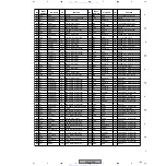
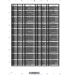
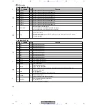
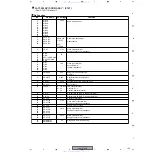
(8) Power supply and ground pins
No.
Pin Name
I/O
Function
Active
5, 31, 52, 63,
78, 95, 127,
140, 166, 187
3.3VDD
−
3.3V power supply
3.3V positive power supply pins. Power supply for 3.3V interface I/O.
−
14, 67,
118, 170
2.5VDD
−
2.5V power supply
2.5V positive power supply pins. Power supply for internal each block.
−
39, 91,
144, 195
2.5GND
−
Ground pins
Connect all GND pins to the common ground.
−
9, 35, 56, 68,
82, 99, 131,
148, 173, 188
3.3GND
−
199
PLLAVDD
−
Analog power supply for multiply circuit
Analog positive power supply pin for PLL. Supply 2.5V.
−
200
PLLAGND
−
Analog ground for multiply circuit
Analog ground for PLL
−
198
PLLDVDD
−
Digital power supply for multiply circuit
Digital positive power supply pin for PLL. Supply 2.5V.
−
201
PLLDGND
−
Digital ground for multiply circuit
Digital ground for PLL
−
121
IC (H)
−
Internally connected pin
Connect to VDD directly.
−
197, 203,
205-207
IC (L)
−
Internally connected pin
Connect to ground directly.
−
152, 154, 204 IC (PL)
−
Internally connected pin
Connect to ground through a resistor.
−
100, 122
IC (O)
−
Internally connected pin
Set to open.
−
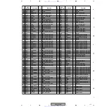
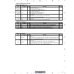
(9) Others
No.
Pin Name
I/O
Function
Active
153
DV_INT
I/O
Interrupt pin to the outside for the DV status read out.
H
155
BR_MON
I/O
Shows the bus reset occurred. There is some delay after real bus reset occurred
because of set by the built-in firmware.
H
208
IFIROME
I
ROM operation selection input
Set to 1 normally.
−
www. xiaoyu163. com
QQ 376315150
9
9
2
8
9
4
2
9
8
TEL 13942296513
9
9
2
8
9
4
2
9
8
0
5
1
5
1
3
6
7
3
Q
Q
TEL 13942296513 QQ 376315150 892498299
TEL 13942296513 QQ 376315150 892498299


