background image


DEH-P440/XN/UC

A

B

C

D

1

2

3

4

1

2

3

4


4


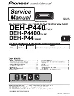
2. EXPLODED VIEWS AND  PARTS LIST


2.1  PACKING


PACKING PARTS LIST

N

OTES : • Parts marked by  "*"  are generally unavailable because they are not in our Master Spare Parts List.                

  • Screw adjacent to    mark on the product are used for disassembly.
  • For the applying amount of lobricants or glue, follow the instructions in this manual.
    (In the case of no amount instructions,apply as you think it appropriate.)

"

4

7

11

3

10

9

8

6

5

16

2

17

12

15

14

13

1

18

19

20

21

22


Mark

NO

Symbol and 
Description

 DEH-P440/XN/UC

DEH-P4400/XN/UC

DEH-P44/XN/UC

1-1

Owner's Manual

CRD3542

CRD3543 

CRD3543

1-2

Installation Manual

CRD3556

CRD3557 

CRD3557


*


1-3

Card

Not used

ARY1048

ARY1048


*


1-4

Warranty Card

CRY1070

Not used

Not used

1-5

Polyethylene Bag

CEG1116

CEG1116

CEG1116

2

Cord Assy

CDE6436

CDE6436

CDE6436

3

Spring

CBH1650

CBH1650

CBH1650

4

Screw Assy

CEA2796

CEA2796

CEA2796

5

Screw

CBA1002

CBA1002

CBA1002


*


6

Polyethylene Bag

CEG-127

CEG-127

CEG-127

Содержание DEH-P44

Страница 1: ...al should be used together with the following manual s Model No Order No Mech Module Remarks CX 977 CRT2624 S9 CD Mech Module Circuit Description Mech Description Disassembly K ZZU2000 printed in Japan CONTENTS 1 SAFETY INFORMATION 3 2 EXPLODED VIEWS AND PARTS LIST 4 3 BLOCK DIAGRAM AND SCHEMATIC 12 4 PCB CONNECTION DIAGRAM 26 5 ELECTRICAL PARTS LIST 34 6 ADJUSTMENT 40 7 GENERAL INFORMATION 48 7 1...

Страница 2: ...e to proper portions by the appropriate amount For replacement parts or tools the prescribed ones should be used 4 Shipping mode and shipping screws To protect the product from damages or failures that may be caused during transit the shipping mode should be set or the shipping screws should be installed before shipping out in accordance with this manual if necessary 1 Product safety You should co...

Страница 3: ...this manual Improperly performed repairs can adversely affect the safety and reliability of the product and may void the warranty If you are not qualified to perform the repair of this product properly and safely you should not risk trying to do so and refer the repair to a qualified service technician WARNING This product contains lead in solder and certain electrical parts contain chemicals whic...

Страница 4: ...t instructions apply as you think it appropriate 4 7 11 3 10 9 8 6 5 16 2 17 12 15 14 13 1 18 19 20 21 22 Mark NO Symbol and Description DEH P440 XN UC DEH P4400 XN UC DEH P44 XN UC 1 1 Owner s Manual CRD3542 CRD3543 CRD3543 1 2 Installation Manual CRD3556 CRD3557 CRD3557 1 3 Card Not used ARY1048 ARY1048 1 4 Warranty Card CRY1070 Not used Not used 1 5 Polyethylene Bag CEG1116 CEG1116 CEG1116 2 Co...

Страница 5: ... CHG4557 CHG4553 CHG4556 14 Contain Box CHL4557 CHL4553 CHL4556 15 Protector CHP2251 CHP2251 CHP2251 16 Protector CHP2252 CHP2252 CHP2252 17 Case Assy CXB3520 CXB3520 Not used 18 Screw BPZ20P060FZK BPZ20P060FZK BPZ20P060FZK 19 Remote Control Unit CXB8743 CXB8743 CXB6797 20 Battery CEX1065 CEX1065 CEX1065 21 Accessory Assy CEA2773 CEA2773 CEA2773 22 Earth Plate CNC9450 CNC9450 CNC9450 Mark NO Symbo...

Страница 6: ...DEH P440 XN UC A B C D 1 2 3 4 1 2 3 4 6 2 2 EXTERIOR ...

Страница 7: ...6 42 Lighting Conductor CNV6487 43 Gear CNV6507 44 Arm CNV6508 45 Panel Unit CWM7375 46 Socket CN1950 CKS3550 47 Connector CN1951 CKS4206 48 Damper Unit CXB5070 49 Holder Unit CXB6356 50 Holder Unit CXB6357 51 Clutch Unit CXB6358 52 Screw IMS20P045FZK 53 Detach Grille Assy See Contrast table 2 54 Screw BPZ20P100FZK 55 Button 1 6 SOURCE CAC7225 56 Button OPEN CAC7227 57 Button SFEQ CAC7221 58 Butto...

Страница 8: ...ucted the same except for the following Mark NO Symbol and Description DEH P440 XN UC DEH P4400 XN UC DEH P44 XN UC 14 Tuner Amp Unit CWM8015 CWM8014 CWM8014 53 Detach Grille Assy CXB8406 CXB8407 CXB8408 63 Knob CAA2725 CAA2699 CAA2699 70 Keyboard Unit CWM8308 CWM8308 CWM8310 77 Sub Grille Assy CXB8614 CXB8615 CXB8616 ...

Страница 9: ...DEH P440 XN UC A B C D 5 6 7 8 5 6 7 8 9 ...

Страница 10: ...DEH P440 XN UC A B C D 1 2 3 4 1 2 3 4 10 2 3 CD MECHANISM MODULE D ...

Страница 11: ...NC9017 38 Bracket CNC9123 39 Frame CNC9656 40 Belt CNT1086 41 Gear CNV6886 42 Gear CNV6316 43 Gear CNV6317 44 Gear CNV6318 45 Gear CNV6319 46 Gear CNV6320 47 Arm CNV6322 48 Arm CNV6323 49 Arm CNV6324 50 Arm CNV6888 51 Arm CNV6889 52 Guide CNV6327 53 Arm CNV6924 54 Guide CNV6921 55 Rack CNV6923 56 Clamper CNV6331 57 Arm CNV6332 58 Guide CNV6333 59 Cover CNV6334 60 Arm CNV6335 61 Guide CNV6336 62 Ro...

Страница 12: ...AM 1ST IF 10 7MHz T51 Q51 CF51 CF52 CF53 IC1 MIXER IF AMP DET LDET COMP CF202 VCC DI DO CE2 CK CE1 SDBW SL FMSD NL1 NL2 IC 2 FM MPX AMANT FMANT ATT ATT AMRF FMRF IMG ADJ RF ADJ X901 10 25MHz ANT ADJ LOCL LOCH AMDET MPXREF 41kHz AM 2ND IF 450kHz CREQ STIND L ch 1 s 39 14 25 23 Q410 LOCL VCC LOCH 50 51 L L B U 5 R ch 7 17 20 24 26 WC NC NC FMLOCL RFGND 11 DGND 10 VDD VDD 9 NC PDIO Q910 mute Q362 Q9 ...

Страница 13: ...Q914 Q359 Q351 SYSPW Q1905 Q917 B U 1 2 TX RX IPPW TX RX IPPW ELECTRONIC VOLUME SOURCE SELECTOR 77 CSENS ILMPW B U VDD B REM STBY MUTE REMOTE CONTROL SENSOR IC 1903 PD6294A LCD DRIVER KEY MATRIX LCD OPT IN 1 9 8 7 10 3 5 6 4 11 7 10 11 14 12 13 2 7 8 4 8 5 5 FILM 6 6 9 9 4 10 11 14 12 13 2 4 3 6 5 10 8 7 9 2 3 DPDT KYDT X0 X1 DIMMER KEY DATA LCD DATA REMIN VDD 9 8 3 X1901 2 7 23 10 CN750 CN1951 CN...

Страница 14: ...m Guide page Detailed page Note When ordering service parts be sure to refer to EXPLODED VIEWS AND PARTS LIST or ELECTRICAL PARTS LIST A a DETACH SENSE S DSP 201M PE5246A CD 4 1dBs D CONTROL UNIT P4400 P44 FM 100 19 5dBs AM 30 30dBs B C PANEL UNIT KEYBOARD UNIT FM AM TUNER UNIT SYSTEM CONTROLLER The mark fo the importance Therefore whe identical desig EJECT ...

Страница 15: ...M 100 19 5dBs AM 30 30dBs CD 4 1dBs IP BUS 2 2dBs CD 9 4dBs NIT SYSTEM CONTROLLER CEK1136 10A FUSE 600µH A TUNER AMP UNIT For resistors and capacitors in the circuit diagrams their resistance values or capacitance values are expressed in codes Ex Resistors Code Practical value 123 12k ohms 103 10k ohms Capacitors Code Practical value 103 0 01uF 101 10 100uF 10V The mark found on some component par...

Страница 16: ...DEH P440 XN UC A B C D 1 2 3 4 1 2 3 4 16 1 2 A a A b A a A b DSP 201M PE5246A P4400 P44 FM 100 19 5dBs AM 30 30dBs FM AM TUNER UNIT SYSTEM CONTROLLE ...

Страница 17: ...DEH P440 XN UC A B C D 5 6 7 8 5 6 7 8 17 2 3 A a A b A a A b B DETACH SENS CD 4 1dBs D CONTROL UNIT B C PANEL UNIT KEYBOARD UNIT SYSTEM CONTROLLE T th T id EJECT ...

Страница 18: ... only PML009A P440 PML008A P4400 P44 P440 only P440 only P440 only P4400 P44 P4400 P44 P440 only 472 16 IP BUS 2 2dBs FM 100 3 6dBs AM 30 6 9dBs CD 10 2dBs IP BUS 10 3dBs FM 100 19 5dBs AM 30 30dBs CD 4 1dBs IP BUS 2 2dBs CD 9 4dBs STEM CONTROLLER CEK1136 10A FUSE 600µH A TUNER AMP UNIT ...

Страница 19: ...apacitors in the circuit diagrams their resistance values or capacitance values are expressed in codes Ex Resistors Code Practical value 123 12k ohms 103 10k ohms Capacitors Code Practical value 103 0 01uF 101 10 100uF 10V The mark found on some component parts indicates the importance of the safety factor of the part Therefore when replacing be sure to use parts of identical designation ...

Страница 20: ...BOARD UNIT CAW1628 CLK Model DEH P440 XN UC DEH P4400 XN UC DEH P44 XN UC DEH P440 XN UC DEH P4400 XN UC DEH P44 XN UC Model S1902 S1904 S1906 S1909 S1919 CSG1107 CSG1117 DEH P440 XN UC DEH P4400 XN UC DEH P44 XN UC Model S1901 S1907 CSG1107 CSG1133 C ...

Страница 21: ...DEH P440 XN UC A B C D 5 6 7 8 5 6 7 8 21 CLK CSG1111 B CN1951 C KEYBOARD UNIT C ...

Страница 22: ...LOADING CARRIAGE SPINDLE RF AMP SERVO CON ACT MOTOR DRIVER 5V REGULATOR CN101 TC9495 SWITCHES CONTROL S901 HO S902 CLA S903 DS S904 12E S905 8EJ The under D Symbol indicate No differentiatio discrete resistors NOTE Symbol indicate No differentiatio discrete capacito PICKUP UNIT SERVICE P9 ...

Страница 23: ...04 12EJ SWITCH ON OFF S905 8EJ SWITCH ON OFF The underlined indicates the switch position D A Decimal points for resistor and capacitor fixed values are expressed as 2 2 2R2 0 022 R022 Symbol indicates a resistor No differentiation is made between chip resistors and discrete resistors NOTE Symbol indicates a capacitor No differentiation is made between chip capacitors and discrete capacitors D CON...

Страница 24: ...Normal Ref GND Mode Normal Ref VREF Mode Normal Ref VREF Mode Normal Ref VREF Mode Normal Ref VREF Mode Normal Ref VREF Mode Normal Ref VREF Mode Normal Ref VREF Mode Normal Ref VREF Mode Test Ref VREF Mode Normal Ref VREF Mode Normal 500ms div 0 CH1 TE 500mV div 8 CH2 FE 500mV div When setting up Source On 200ms div 1µs div CH1 LRCK 2V div CH2 DOUT 2V div During Play 10µs div 7 CH1 MD 500mV div D...

Страница 25: ...ms div 1 CH1 DSCSNS 5V div 2 CH2 CLCONT 5V div 3 CH3 LOEJ 5V div When Eject 8cm CD 200ms div CH1 TEY 500mV div CH2 SD 2V div During inside outside search 200ms div 1 CH1 DSCSNS 5V div 2 CH2 CLCONT 5V div 3 CH3 LOEJ 5V div When Eject 12 cm CD 200ms div CH1 RFO 2V div CH2 DFCT 5V div 5 CH3 FD 1V div CH4 TD 2V div When reproducing black dots 800µm 500µs div Ref VREF Mode Test Ref VREF Mode Test Ref V...

Страница 26: ... CN701 D Capacitor Connector P C Board Chip Part A A TUNER AMP UNIT SIDE B SIDE A NOTE FOR PCB DIAGRAMS 1 The parts mounted on this PCB include all necessary parts for several destination For further information for respective destinations be sure to check with the schematic dia gram 2 Viewpoint of PCB diagrams ...

Страница 27: ...DEH P440 XN UC A B C D 5 6 7 8 5 6 7 8 27 REAR OUTPUT ANTENNA JACK FM AM TUNER UNIT FRONT CN1950 B IP BUS INPUT CORD ASSY A SIDE A ...

Страница 28: ...DEH P440 XN UC A B C D 1 2 3 4 1 2 3 4 28 A A TUNER AMP UNIT ...

Страница 29: ...DEH P440 XN UC A B C D 5 6 7 8 5 6 7 8 29 A SIDE B ...

Страница 30: ...DEH P440 XN UC A B C D 1 2 3 4 1 2 3 4 30 4 2 PANEL UNIT EJECT C CN1901 B B PANEL UNIT B PANEL UNIT SIDE A SIDE B A CN750 ...

Страница 31: ...DEH P440 XN UC A B C D 5 6 7 8 5 6 7 8 31 4 3 KEYBOARD UNIT CLK DISPLAY VOLUME EQ SOURCE 1 2 3 4 5 6 BAND SFE AUDIO FUNCTION C C KEYBOARD UNIT C KEYBOARD UNIT SIDE A SIDE B B CN1951 ...

Страница 32: ...DEH P440 XN UC A B C D 1 2 3 4 1 2 3 4 32 4 4 CD MECHANISM MODULE 12EJ DSCSNS HOME D D CONTROL UNIT SIDE A A CN501 M2 LOADING CARRIAGE MOTOR M1 SPINDLE MOTOR PICKUP UNIT SERVICE P9 ...

Страница 33: ...DEH P440 XN UC A B C D 5 6 7 8 5 6 7 8 33 CLAMP 8EJ D D CONTROL UNIT SIDE B ...

Страница 34: ...2 Transistor DTC114EK Q 913 Transistor 2SD1760F5 Q 914 Transistor 2SC2412K Q 915 Transistor 2SC2412K Q 917 Transistor 2SC2412K Q 918 Transistor 2SC2412K D 320 Diode DAN202U D 361 Diode S5688G D 362 Diode S5688G A D 510 Diode HZS9L B1 D 750 Diode 1SS270 D 751 Diode 1SS270 D 752 Diode DAP202U D 753 Diode DAN202U D 754 Diode DAP202K D 755 Diode DAN202K D 762 Diode DAN202U D 763 Diode DAP202U D 910 Di...

Страница 35: ...531 RS1 16S0R0J R 532 RS1 16S0R0J R 536 RS1 16S102J R 537 RS1 16S104J R 610 RS1 16S473J Circuit Symboland No Part Name Parts No R 611 DEH P4400 P44 RS1 16S473J R 612 RS1 16S2202F R 613 RS1 16S102J R 614 RS1 16S821J R 615 RS1 16S102J R 616 RS1 16S0R0J R 620 RS1 16S473J R 621 RS1 16S0R0J R 622 RS1 16S101J R 624 RS1 16S104J R 625 RS1 16S0R0J R 626 RS1 16S473J R 627 RS1 16S473J R 628 RS1 16S473J R 630...

Страница 36: ... 343 CEJA2R2M50 C 351 DEH P4400 P44 CEJA2R2M50 C 352 DEH P4400 P44 CEJA2R2M50 C 361 4700µF 16V CCH1367 Circuit Symboland No Part Name Parts No C 362 CKSQYB104K16 C 363 CKSQYB474K16 C 364 CKSQYB474K16 C 365 CKSQYB474K16 C 366 CKSQYB474K16 C 367 CKSQYB474K16 C 368 CKSQYB474K16 C 369 CKSQYB474K16 C 370 CKSQYB474K16 C 371 CEJA330M10 C 373 CKSQYB225K10 C 374 CKSQYB225K10 C 375 CEJA100M16 C 410 CKSQYB10...

Страница 37: ...07 S 1910 Switch DEH P44 CSG1117 S 1911 Switch DEH P440 P4400 CSG1107 S 1911 Switch DEH P44 CSG1117 S 1912 Switch DEH P440 P4400 CSG1107 S 1912 Switch DEH P44 CSG1117 S 1913 Switch DEH P440 P4400 CSG1107 S 1913 Switch DEH P44 CSG1117 Circuit Symboland No Part Name Parts No C S 1914 Switch DEH P440 P4400 CSG1107 S 1914 Switch DEH P44 CSG1117 S 1915 Switch DEH P440 P4400 CSG1107 S 1915 Switch DEH P4...

Страница 38: ...R 303 RS1 16S332J R 304 RS1 16S514J Circuit Symboland No Part Name Parts No B D R 306 RS1 16S102J R 307 RS1 16S102J R 312 RS1 16S103J R 313 RS1 16S473J R 315 RS1 16S334J R 321 RS1 16S331J R 322 RS1 16S0R0J R 323 RS1 16S332J R 401 RS1 16S684J R 402 RS1 16S103J R 403 RS1 16S103J R 404 RS1 16S183J R 405 RS1 16S123J R 407 RS1 16S622J R 408 RS1 16S622J R 409 RS1 16S113J R 410 RS1 16S752J R 701 RS1 16S1...

Страница 39: ... C 328 CKSRYB472K50 C 329 CKSRYB104K16 C 330 CKSRYB104K16 C 331 CKSRYB104K16 C 401 CKSRYB221K50 C 402 CKSRYB221K50 C 403 CKSRYB153K25 C 404 CKSRYB103K50 C 405 CEV101M10 C 702 CKSRYB104K16 C 703 CKSRYB104K16 C 801 10µF 10V CCH1349 C 802 CEV101M10 C 803 CKSRYB224K16 Miscellaneous Parts List Pickup Unit Service P9 CXX1480 M 1 Motor Unit SPINDLE CXB6007 M 2 Motor Unit LOADING CARRIAGE CXB5903 Circuit ...

Страница 40: ...r run for about one minute to allow the circuits to stabi lize Since the protective systems in the unit s software are rendered inoperative in test mode be very careful to avoid mechanical and or electrical shocks to the sys tem when making adjustment The RFI and RFO signals are easy to oscillate because of a wide band When observing them insert a resis tor of about 1 kΩ to the series This equipme...

Страница 41: ... New Test Mode 2 Automatic adjustment value display switching 3 TRK MIN SEC 1 T CLS and F T AGC and RF AGC and Applicable servomechanism TRKxxMINxxSECxx 6 T Close and Applicable servomechanism TRKxxMINxxSECxx 3 RF AGC RF AGC coefficient display TRK MIN SEC CRG TRK8x MIN8x SEC8x or TRK9xMIN9xSEC9x CRG TRK8xMIN8xSEC8x or TRK9xMIN9xSEC9x 2 T Balance adjustment T Balance coefficient display TRK MIN SE...

Страница 42: ...nd switch the 5V regulator on 2 Using the and buttons move the PU unit to the innermost track 3 Press key 3 to close focus the display should read 91 Press key 2 to implement the tracking balance adjust ment the display should now read 81 Press key 3 The display will change returning to 81 on the fourth press 4 As shown in the diagram above monitor the LPF outputs using the oscilloscope and check ...

Страница 43: ...DEH P440 XN UC A B C D 5 6 7 8 5 6 7 8 43 Grating waveform Ech Xch 20mV div AC Fch Ych 20mV div AC 45 0 75 60 30 90 ...

Страница 44: ...ove mechanism Communication error between microcomputer and SERVO LSI 11 Electricity Focus Servo NG Focusing not available Stains on rear side of disc or excessive vibrations on REWRITABLE 12 Electricity Spindle Lock NG Spindle not locked Sub code is strange not readable Subcode NG Failure on spindle stains or damages on disc or excessive vibrations A disc not containing CD R data is found Turned ...

Страница 45: ...he new test mode by turning on the reset start 2 Key Correspondence Key Test mode New test mode Regulator Off Regulator On In play Error Production BAND To regulator on To regulator off Time Err No switching FWD Kick FF TR REV Kick REV TR 1 Tracking Close Scan 2 Tracking Open Mode 3 Focus Close Focus Open Jump Off 6 To new test mode Jump mode switching Auto Manu Note Eject and CD on off is perform...

Страница 46: ...32 Tracking close start Spindle stationary servocontrol setting Focus slips off 33 Tracking close 2 Focus slips off 34 Tracking close 3 Focus slips off 35 Focus Tracking AGC start Focus slips off 36 Focus Tracking AGC 2 Focus slips off 37 Focus Tracking AGC 3 Focus slips off 38 Focus Tracking AGC 4 Focus slips off 39 Focus Tracking AGC 5 Focus slips off 40 Focus Tracking AGC 6 Focus slips off 41 F...

Страница 47: ... in the normal mode 3 When a Protection Error Occurred A Error display A B C BAND key 8 digit display 6 digit display 4 digit display ERROR xx ERR xx E xx B Error occurrence timing display in track no B C Auto Manual key 8 digit display 6 digit display 4 digit display Auto setting TNO Min Sec TNO 10 40 05 10 C Error occurrence timing display in absolute time B C Auto Manual key 8 digit display 6 d...

Страница 48: ...e screws and then remove the Tuner Amp Unit Tuner Amp Unit is different partially from this photo Removing the Case not shown 1 Remove the Case Removing the CD Mechanism Module Fig 1 Remove the four screws Disconnect the connector and then remove the CD Mechanism Module Removing the Grille Panel Assy Fig 1 Remove the two screws and then r Grille Panel Assy Fig 1 Fig 2 Tuner Amp Unit CD Mechanism M...

Страница 49: ...es of Damper while slowly pulling up the part 4 Now the top frame has been removed and under this state fix the genuine Connector again and eject the disk Caution When you reassemble the Carriage Mechanical part apply a bit of alcohol to Dampers How to remove the Guide Arm Assy 1 Unlock the spring 1 piece at the right side of the assembly 2 Unscrew screws 2 pieces then remove the Screw Gear Bracke...

Страница 50: ... spring 1 piece and remove the E ring 1 piece of the Fulcrum Shaft 2 Shift the arm to the left side direction and unlock pins 2 pieces How to remove the Pickup Unit 1 Unscrew 2 pieces of screws then remove the Pulley Cover 2 Remove the Feed Screw unit from the pawl of the Feed Screw Guide The pawl is located inside the guide 3 Remove the belt from the Pulley then remove the Pickup unit Caution Mak...

Страница 51: ... 9 8 7 6 5 4 3 2 1 RCA BUSH 15 16 10 2 5 1 REAR OUTPUT ANTENNA JACK FUSE 10A 1 BUS 2 GND 3 GND 4 NC 5 BUS 6 GND 7 BUS L INPUT 8 ASENB 9 BUS R INPUT 10 BUS R INPUT 11 BUS L INPUT FRONT OUTPUT 1 GND 2 B UP 3 ACC 4 NC 5 ILM 6 B REM 7 NC 8 NC 9 RL 10 FL 11 RL 12 FL 13 RR 14 FR 15 RR 16 FR ...

Страница 52: ...S GND 14 IN4 15 IN3 16 AC GND 17 OUT3 18 P GND3 19 OUT3 20 VCC 21 OUT4 22 MUTE 23 OUT4 24 P GND4 SWITCH 25 Offset Detection Offset Detection Offset Detection Offset Detection Protector Over current limit sw_vcc stby Protector Short circuit Mute circuit amp_vcc Stand by Circuit Protector Over voltage sw_vcc Protector Thermal Reference amp_vcc PAL007A ...

Страница 53: ...r Anti Radiation Filter 0 5dB shift volume Primary Volume Anti Alias Filter Bass Middle Treble ASL Loudness Volume Phase control LPF Rch Block same as Lch Zero Cross detector PML009A DEH P440 XN UC DGND CLK Vref NC MUTE STB DATA IN4 _R IN4 _R IN3_R IN1_R IN2_R Vcc IN1_L IN2_L IN3_L IN4 _L IN4 _L 12 11 10 9 8 7 6 5 4 3 2 1 20 19 18 17 16 15 14 13 30 29 28 27 26 25 24 23 22 21 40 39 38 37 36 35 34 3...

Страница 54: ...ply control output for IP BUS interface IC 25 ROT1 I Rotary input 1 26 31 NC Not used 32 pce O EEPROM chip enable output 33 STB O Strobe pulse output for electronic volume 34 CLK O Clock output for electronic volume 35 DATA O Data output for electronic volume 36 NC Not used 37 MUTE O System mute output 38 SD I Station detector input 39 st I FM stereo input 40 VSS GND GND 41 VDD Power supply 42 fm ...

Страница 55: ...3 AVREF A D converter reference voltage terminal 84 AVSS GND 85 RX I IP BUS data input 86 TX O IP BUS data output 87 NMI GND 88 ldet I PLL lock sense input 89 91 NC Not used 92 asens I ACC power sense input 93 bsens I Back up power sense input 94 TUNPDI I PLL IC data input 95 KYDT I Grille data input 96 DPDT O Grille data output 97 PCK O PLL IC clock output 98 PDO O PLL IC data output 99 PCE O PLL...

Страница 56: ...ect to GND 7 DIMMER O Dimmer select output 8 KYDT O Key data output 9 DPDT I Display data input 10 REMIN I Remote control pulse input 11 GRN Dual Illumination Green 12 AMB Dual Illumination Amber 13 16 KD4 1 I Key data input 17 22 KST6 1 O Key strobe output 23 VDD VDD 24 73 SEG49 0 O LCD segment output 74 77 COM3 0 O LCD common output 78 VLCD I LCD voltage input 79 80 V2 1 Power supply terminal PD...

Страница 57: ...rminal 14 TEO O Tracking error signal generation amplifier output terminal 15 SBAD O Sub beam addition signal output terminal 16 FEO O Focus error signal generation amplifier output terminal 17 FEN I Focus error signal generation amplifier reverse phase input terminal 18 SEB I RFRP generation circuit mode switching terminal 19 VRO O Reference voltage VREF output terminal 20 RFRP O Signal generatio...

Страница 58: ...OWVCC1 Power supply pin for CH1 CH2 and CH3 at Power stage 11 VO1 Driver CH1 Negative output 12 VO1 Driver CH2 Positive output 13 VO2 Driver CH2 Negative output 14 VO2 Driver CH2 Positive output 15 VO3 Driver CH2 Positive output 16 VO3 Driver CH2 Negative output 17 VO4 Driver CH4 Positive output 18 VO4 Driver CH4 Negative output 19 POWVCC2 Power supply pin for CH4 at Power stage 20 GND Ground pin ...

Страница 59: ... ZDET O One bit DAC zero detection flag output terminal 28 PDO O Phase error signal issue between the EFM and PLCK signals 29 TMAXS O TMAX detection result output terminal 30 TAMX O TMAX detection result output terminal 31 LPFN I Reverse input terminal of amplifier for lowpass filter 32 LPFO O Output terminal of amplifier for lowpass filter 33 PVREF PLL system only VREF terminal 34 VCOREF I VCO ce...

Страница 60: ...ower supply terminal 5 V 77 XVSS Ground terminal for system clock oscillator circuit 78 XI I System clock oscillator circuit input terminal 79 XO O System clock oscillator circuit output terminal 80 XVDD For system clock oscillator circuit power supply terminal 81 DVSR R channel D A converting unit power supply terminal 82 RO O R channel data forward rotation output terminal 83 DVDD D A converting...

Страница 61: ...ut To be pulled up to the VDD at 47kΩ 16 CE1 I chip enable 1 AF RF chip enable Active at High To be grounded at 47kΩ 17 NC Not used 18 LDET O lock detector Active at Low To be pulled up to the VDD at 47kΩ 19 CREQ I current request Active at Low To be grounded at 47kΩ 20 NC Not used 21 COMP O composite signal FM composite signal output r out 100Ω 22 VCC power supply Analog section power supply pin ...

Страница 62: ...EG20 SEG21 SEG22 SEG23 SEG24 SEG25 SEG26 SEG27 SEG28 SEG29 SEG10 SEG11 SEG12 SEG13 SEG14 SEG15 SEG16 SEG17 SEG18 SEG19 SEG 9 SEG 8 SEG 7 SEG 6 SEG 5 SEG 4 SEG 3 SEG 2 SEG 1 SEG 0 COM0 COM1 COM2 COM1 COM0 COM1 COM2 COM1 COM0 6 6 5 4 3 2 1 5 4 3 2 1 5 4 3 2 1 5 4 3 2 1 5 4 3 2 1 5 4 3 2 1 5 4 3 2 1 5 4 3 2 1 5 4 3 2 1 6 5 4 3 2 1 1 2 1 2 3 4 5 6 7 8 9 0 1 2 3 4 5 6 7 8 9 0 1 2 3 4 5 6 7 8 9 0 1 2 3 ...

Страница 63: ... that proceed to each source operation SYSPW H 21pin Starts communication with Grille microcomputer Source ON 300ms 300ms In case of the above signal the communication with Grille microcomputer may fail If the time interval is not 300msec the oscillator may be defective CSENS 77pin 2V CSENS 4V 2V CSENS 4V Source returns to the original one before you open CD MD and TAPE loading functions are avail...

Страница 64: ...2 3 4 64 7 4 CLEANING Before shipping out the product be sure to clean the following portions by using the perscribed cleaning tools Portions to be cleaned Cleaning tools CD pickup lenses Cleaning liquid GEM1004 Cleaning pater GED 008 ...

Страница 65: ...ct a natural sound with pres ence 7 BAND ESC button Press to select among three FM or AM bands and cancel the control mode of functions 8 1 6 PRESET TUNING buttons Press for preset tuning and disc number search when using a multi CD player 9 SOURCE button This unit is switched on by selecting a source Press to cycle through all of the available sources 0 EQ button Press to select various equalizer...

Страница 66: ... nation of the head unit about the operation of each button with the exception of ATT which is explained below 2 FUNCTION button Press to select functions button Raise or lower the volume CD button Press once to select a CD PAUSE button Press once to pause play TUNER button Press once to select a tuner ATT button Press to quickly lower the volume level by about 90 Press once more to return to the ...

Страница 67: ... not connect anything to the speaker leads that are not connected to speakers Yellow To terminal always supplied with power regardless of ignition switch position Black ground To vehicle metal body Red To electric terminal controlled by ignition switch 12 V DC ON OFF Orange white To lighting switch terminal Rear Speaker Rear Speaker Front speaker Front speaker Rear Speaker Rear Speaker Power amp s...

Страница 68: ... kHz High 11 dB 100 Hz 11 dB 10 kHz volume 30 dB Tone controls Bass Frequency 40 63 100 160 Hz Level 12 dB Treble Frequency 2 5k 4k 6 3k 10k Hz Level 12 dB HPF DEH P440 XN UC Frequency 50 80 125 Hz Slope 12 dB oct Subwoofer output Frequency 50 80 125 Hz Slope 18 dB oct Gain 12 dB CD player System Compact disc audio system Usable discs Compact disc Signal format Sampling frequency 44 1 kHz Number o...

Отзывы: