background image

6

<DRB1215>

En

CONNECTIONS

BEFORE OPERATIONS

POWER CORD CONNECTIONS

After all other connections are made, connect the power
cord to a household wall outlet or to the auxiliary AC
power takeoff on your amplifier.

÷

Make sure plugs are fully inserted into the jacks and
wall outlet.

NOTE:
If you do the following actions when the disc is spinning
in the unit, the unit may malfunction.

1) Set the power switch to off, then on.
2) Disconnect the power cord, then connect again.

To correct, press the EJECT button to stop the disc. You
may then resume player operation.

POWER-CORD CAUTION

Handle the power cord by the plug. Do not pull out the
plug by tugging the cord and never touch the power cord
when your hands are wet as this could cause a short
circuit or electric shock. Do not place the unit, a piece of
furniture, etc., on the power cord, or pinch the cord.
Never make a knot in the cord or tie it with other cords.
The power cords should be routed such that they are
not likely to be stepped on. A damaged power cord can
cause a fire or give you an electrical shock. Check the
power cord once in a while. When you find it damaged,
ask your nearest PIONEER authorized service center or
your dealer for a replacement.

R

L

R

L

L

R

LINE INPUT

L

R

L

R

L

R

L

R

PHONO1  CD2/LINE

LINE    CD1

CH2

CH1

PLAYER CONTROL

L

R

L

R

L

R

HEAD-
PHONE

AUDIO
  OUT

CON-
TROL

L
R

HEAD-
PHONE

AUDIO
  OUT

CON-
TROL

L
R

L

L

R

R

CONTROL

PHONO 2
  /LINE 2

PHONO

LINE

CD 2

SIGNAL
  GND

L

L

R

R

CONTROL

PHONO 1
  /LINE 1

PHONO

LINE

CD 1

CDJ-700S

CDJ-700S

DJM-500

DJM-300

CON-
TROL

CON-
TROL

AUDIO
  OUT

AUDIO
  OUT

Audio
cable

Mini-plug control
cable (accessory)

Audio cable

When using relay
play operation

Stereo
amplifier

Mini-plug control
cable (accessory)

÷

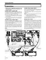
Before making or changing the connections, switch
off the power switch and disconnect the power cord
from the AC outlet.

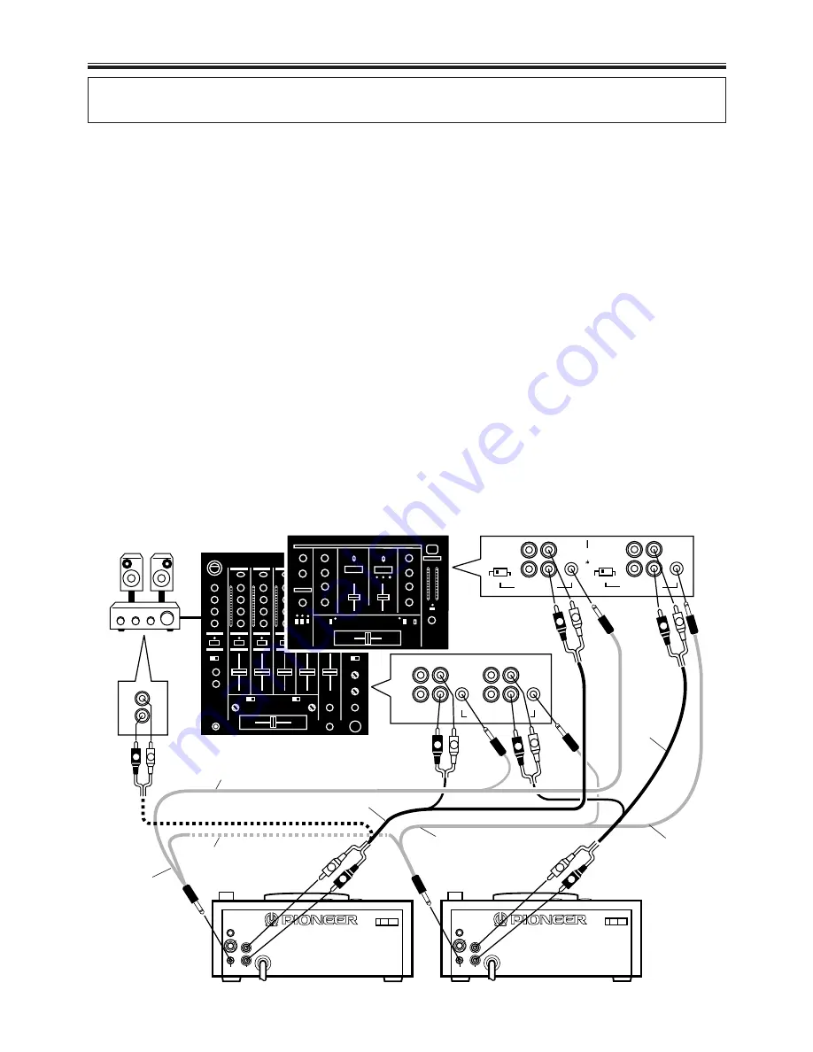
AUDIO OUTPUT CONNECTION

Connect the player’s AUDIO OUT jack to the LINE IN or
AUX IN jack of a DJ mixer or similar component.  Make
sure that the white plugs are connected to the left (L)
jacks and the red plugs to the right (R) jacks.

÷

Do not connect this player to the DJ mixer MIC jacks,
as the sound will be distorted and will not be prop-
erly reproduced.

÷

The illustration shows an example of connections
made when the CDJ-700S is connected to the DJM-
300 or DJM-500.

CONTROL JACK CONNECTIONS

Connect both CONTROL jacks of two players with the
accessory mini-plug cable. By connecting two players,
continuous playback on both players can be carried out
alternately.  (Refer to page 12.)
By connecting the optional DJM-500 or DJM-300 DJ
mixer to the CONTROL jack of this unit, the fader start-
ing or back cuing of this unit can be controlled from the
audio mixer. For the connection and operation, read the
operating instructions of the DJM-500 or DJM-300 DJ
mixer.
NOTE:
Fader start and relay play cannot be performed simulta-
neously, since different control cable connections are
required.

When using fader
start operation

When using fader
start operation

Содержание CDJ-700S

Страница 1: ... from that to which the receiver is connected Consult the dealer or an experienced radio TV technician for help CAUTION This product satisfies FCC regulations when shielded cables and connectors are used to connect the unit to other equipment To prevent electromagnetic interference with electric appliances such as radios and televisions use shielded cables and connectors for connections For Canadi...

Страница 2: ... will only fit into a grounding type power outlet Thisisasafetyfeature Ifyouareunabletoinsertthe plug into the outlet contact your electrician to replace your obsolete outlet Do not defeat the safety purpose of the grounding type plug POWER CORD PROTECTION Power supply cords should be routed so that they are not likely to be walked on or pinched by items placed upon or against them paying particul...

Страница 3: ...2 e J he J e J he h J H hJ e g O2 0Y e 0Yg O2 0M e 7 he 75 e 75 he hW he7 5 J Le O2 0Mg V4 0Mh O2 0Mf e he H e H he g W he H W 2 0M O2 Mh N e he e e hf gW X he 5 W M O2 0M H he e he e 3 hf f W V g O2 H 7 Y N H O2 g hf e he e V4 5 hf fW f O2 J H e hf W2 6Xe he J Le L h gI4 0Y hf e O 0M eO2 0MW T O2 Lh O W 1e he 7 1e 1 h hf e 0M e 0M e7 V 0M 1f O2 7 e he e h hf W X heO2 eV M f Mg 0Mf 3 W2 0Mf e e he...

Страница 4: ...at humid ity or extremely low temperatures Avoid leaving discs in cars the interior of a car in direct sunlight can become extremely hot Always read and abide by the precautionary notes listed on disc labels Mounting Rack When using a commercially available 19 inch stand ard rack EIA with a sliding shelf use the supplied screws and spacers for mounting the player to the sliding shelf The player s ...

Страница 5: ...dless new possibilities are provided by mastering how to turn loops on and off in conjunction with the music rhythm Short Cut As a subfunction of the reloop func tion unwanted portions of a track can be eliminated and the remainder combined for seamless loop play For example a new track could be cre ated by combining the introduction and ending of an existing track CUE Full cueing functions Back C...

Страница 6: ... CONTROL PHONO 2 LINE 2 PHONO LINE CD 2 SIGNAL GND L L R R CONTROL PHONO 1 LINE 1 PHONO LINE CD 1 CDJ 700S CDJ 700S DJM 500 DJM 300 CON TROL CON TROL AUDIO OUT AUDIO OUT Audio cable Mini plug control cable accessory Audio cable When using relay play operation Stereo amplifier Mini plug control cable accessory Before making or changing the connections switch off the power switch and disconnect the ...

Страница 7: ...11 P 13 9 LOOP OUT EXIT button P 11 P 13 0 RELOOP button P 11 P 13 Headphones jack Level control HEADPHONE HEADPHONE VOLUME Located on rear panel The headphone jack is provided only to allow con firmation of the disc sound as a result the vol ume provided by the headphone output may seem insufficient when listening within a disco or other environment characterized by high sound volume TEMPO contro...

Страница 8: ...or 16 in steps of 0 1 4 MASTER T indicator Lights when the MASTER TEMPO function is used 5 AUTO CUE indicator Lights when the AUTO CUE function is used 6 Playback address display The elapsed playback time or remaining playback time of the track playing is roughly indicated with the full scaled bar graph When no disc is in the disc compartment off When displaying elapsed playback time lights up fro...

Страница 9: ...sh to stop all sound lower the output sound volume on your audio mixer When the unit has not been operated for 80 minutes or more in pause mode the disc rotation stops auto matically In this instance playback can be resumed by pressing the PLAY PAUSE button Track Cueing 7 TRACK SEARCH buttons 4 Press one of the TRACK SEARCH buttons 4 Each time the button is pressed the track is cued in the directi...

Страница 10: ...close 4 Press the PLAY PAUSE button 6 Press this button only after the cue indicator CUE is lit Playback will begin immediately 7 When playback of one track ends the player advances to cue the beginning of the next track and enters the standby mode The cue indicator CUE lights and the 6 indicator flashes indicating the unit is in playback standby mode When the PLAY PAUSE button 6 is pressed the cu...

Страница 11: ...ard or fast reverse will be performed while producing broken or intermittent sound from the disc Standby Frame Search With the unit in standby mode rotate the jog dial slowly Frame search will be performed in 1 frame increments If the dial is rotated at a steady rate in the FWD di rection playback sound will be audible normal speed Cue Standby Cue Point Adjust With the unit in cue standby mode pre...

Страница 12: ...r s fader start operation can also be used to produce cross fader effects Restoring the fader position returns the player to its cue point back cue automatically The following operations are performed on the DJ Mixer For details regarding connections and operation con sult the Operating Instructions furnished with your DJ Mixer 1 Set CROSS FADER switch to ON 2 Set FADER START switch to ON 3 When A...

Страница 13: ...return to the earlier loop press the RELOOP button Loop play will return to the same playback loop canceled in step 3 Technique 3 Real Time Cue and Cue Point Sampler Set a cue point on the fly and sample the currently play ing track 1 During playback press the LOOP IN REAL TIME CUE button 2 Press the CUE button with timing that will give the playback an accent Playback will return to the cue point...

Страница 14: ...ates match the BPM syn chronization is complete 9 Press the CUE button on player CD 2 Player CD 2 will enter standby mode at the cueing point 10 As soon as track A is heard from the speakers press the PLAY PAUSE button 6 on player CD 2 Track B begins playing 11 While checking the sound on the headphones gradu ally move the DJ Mixer s CROSS FADER slider from left to right The sound of track A from ...

Страница 15: ... MIC ter minals Clean away dirt Switch OFF TV set move player away from TV set or plug the player into a separate outlet Replace disc Clean disc Press TIME MODE AUTO CUE button for more than 1 second to set the auto cue function OFF Set the cue point See page 10 Set the cue point See page 10 Turn off POWER of the player or move the player away from the TV or tuner Playback can be started by pressi...

Страница 16: ...below 1 800 872 4159 Please do not ship your product to Pioneer without first calling the Customer Service Department at the above listed number for assistance PIONEER ELECTRONICS SERVICE INC CUSTOMER SUPPORT DIVISION P O BOX 1760 LONG BEACH CA 90801 1760 U S A For warranty information please see the Limited Warranty sheet included with your product Should this product require service in Canada pl...

Отзывы: