background image

3

<ARB7137>

CONTENTS

FEATURES

7

High-power Output of 40W+40W/8

(DIN)

7

Wide-Range Linear Circuit

This new current feedback circuit assures improved oper-
ating stability for flat output impedance and stable driving
of speakers across the full range of frequencies.

7

Low power consumption design.

7

Complementary capacitor pair.

7

Direct Energy MOS Power Amp

Pioneer introduces amp circuitry featuring HEX power
MOS FET devices for high performance. Together with
Pioneer's original Wide Range Linear Circuit technology,
this helps achieve reducing power consumption, while
maintaining the power of current models.
In terms of performance, it contributes to flat damping
factor characteristics across the audio spectrum, and im-
proved power linearity.

INSTALLATION

LOCATION

Install the unit in a well-ventilated location where it
will not be exposed to high temperatures or humid-
ity.

Do not install the unit in a location which is exposed to direct
rays of the sun, or near hot appliances or radiators. Excessive
heat can adversely affect the cabinet and internal compo-
nents.  Installation of the unit in a damp or dusty environment
may also result in a malfunction or an accident.  (Avoid
installation near cookers etc., where the unit may be exposed
to oily smoke, steam or heat.)
Do not install the unit on a tottered stand, nor on an unstable
or inclined surface.

VENTILATION

÷

When installing this unit, make sure to leave space around
the unit for ventilation to improve heat radiation (at least 60
cm at top, 10 cm at rear, and 30 cm at each side). If not
enough space is provided between the unit and walls or
other equipment, heat will build up inside, interfering with
performance or causing malfunctions.

÷

Do not place on a thick carpet, bed, sofa or fabric having a
thick pile. Do not cover with fabric or other covering.
Anything that blocks ventilation will cause internal tem-
perature to rise, which may lead to breakdown or fire
hazard.

FEATURES ......................................................................... 3

INSTALLATION .................................................................. 3

CONNECTIONS .................................................................. 4

PANEL FACILITIES ............................................................. 6

OPERATIONS ..................................................................... 9

TROUBLESHOOTING ...................................................... 11

SPECIFICATIONS ............................................................. 12

Содержание A-107

Страница 1: ...nying the appliance IMPORTANT FOR USE IN THE UNITED KINGDOM The wires in this mains lead are coloured in accordance with the following code Blue Neutral Brown Live If the plug provided is unsuitable for your socket outlets the plug must be cut off and a suitable plug fitted Do not connect either wire to the earth terminal of a three pin plug NOTE After replacing or changing a fuse the fuse cover i...

Страница 2: ...ht to oper ate the equipment POWER CORD CAUTION Handle the power cord by the plug Do not pull out the plug by tugging the cord and never touch the power cord when your hands are wet as this could cause a short circuit or electric shock Do not place the unit a piece of furniture etc on the power cord or pinch the cord Never make a knot in the cord or tie it with other cords The power cords should b...

Страница 3: ... which is exposed to direct rays of the sun or near hot appliances or radiators Excessive heat can adversely affect the cabinet and internal compo nents Installation of the unit in a damp or dusty environment may also result in a malfunction or an accident Avoid installation near cookers etc where the unit may be exposed to oily smoke steam or heat Do not install the unit on a tottered stand nor o...

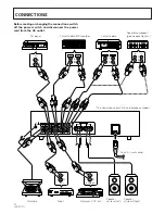
Страница 4: ...ft Speaker system Right CD player Cassette deck Cassette deck MD recorder The illustration shows U K and European models SIGNAL GND L R PHONO IN TUNER IN CD IN LINE IN TAPE 1 MD REC PLAY REC PLAY TAPE 2 MONITOR OUT IN OUT IN L R R L SPEAKERS AC INLET REC PLAY L R REC PLAY L R CD OUT L R IN OUT L R FM AM OUT L R L R L R ª ª L L L R L R R R L R L R L R L R L R L R L R L R L AUDIO OUT L R L R L R L R...

Страница 5: ... Red plug Except for U K European Australian and NewZealand models AC OUTLETS SWITCHED TOTAL 100 W MAX Power supplied through these outlets is turned on and off by the amplifier s POWER switch Total electrical power consumption of connected equipment should not exceed 100 W AC OUTLETS UNSWITCHED 100 W MAX Power flows continually to this outlet regardless of whether the amplifier is switched to ON ...

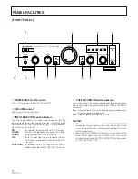
Страница 6: ...ower to the unit ON and OFF 2 VOLUME control Use to adjust the volume level 3 INPUT SELECTOR knob indicators Turn the knob clockwise or counterclockwise so that the indicator lights for your desired input source Turning the knob clockwise causes the lit indicator to right Turning counter clockwise causes it to left CD For compact disc playback with a CD player TUNER For AM or FM broadcast receptio...

Страница 7: ...indicator goes off Should normally be left in this position NOTE This button does not operate when the DIRECT button is in the on position 8 TREBLE tone control Use to adjust the high frequency tone The center position is the flat normal position When turned to the right high frequency tones are emphasized when turned to the left high frequency tones are de emphasized NOTE This control does not op...

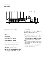
Страница 8: ...e an other power cord than provided we cannot assume the liabilities in what may occur as a result of it The provided power cord has a current capacity of 2 5 A AC OUTLETS see page 5 Except for U K Euro pean Australian and New Zealand models NOTES This unit should be disconnected by removing the power plug from the wall socket when not in regular use e g when on vacation Do not connect appliances ...

Страница 9: ...b 2 Begin recording by operating the recording equip ment and cassette deck Refer to the operating instructions of your cassette deck for proper operating procedures COPYING TAPES When two decks are used you can record the sounds from one deck onto the other Application examples To make a tape copy with contents identical to the original tape To edit a recording of an FM broadcast in order to cut ...

Страница 10: ...f or the power cord is unpluged After this period the CD is automatically selected when the power is supplied For an adaptor component By connecting a graphic equalizer source sounds from discs tapes AM FM broadcasts etc can be heard with added sound and tone compensation Sounds compensated with the adaptor component can be recorded on the cassette deck connected to the TAPE 1 MD terminals 1 Set t...

Страница 11: ...r cords are discon nected on that side BALANCE control is set to one side Connections are incorrect Operation of cassette deck is incorrect The TAPE 2 MONITOR button is set to ON The position of the INPUT SELECTOR knob and TAPE 2 MONITOR button are incorrect when using 2 cassette decks Operation of cassette decks is incorrect Symptom No power supplied to unit No sound No sound from one speaker Can...

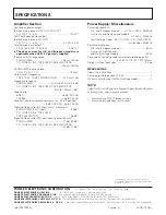
Страница 12: ... 1 MD TAPE 2 MONITOR 200 mV 50 kΩ PHONO MM overload level 1 kHz T H D 0 1 150 mV Output level impedance TAPE 1 REC TAPE 2 MONITOR REC 200 mV 1 kΩ Frequency response PHONO MM 20 Hz to 20 kHz 0 5 dB CD TUNER LINE TAPE 1 MD TAPE 2 MONITOR 5 Hz to 100kHz dB Tone control BASS 8 dB 100 Hz TREBLE 8 dB 10 kHz Loudness contour volume control set at 30 dB position 6 dB 100 Hz 4 dB 10 kHz Signal to Noise rat...

Отзывы: