background image

23

Fr

Fonctionnement

Fran

ç

ais

Fonctionnement

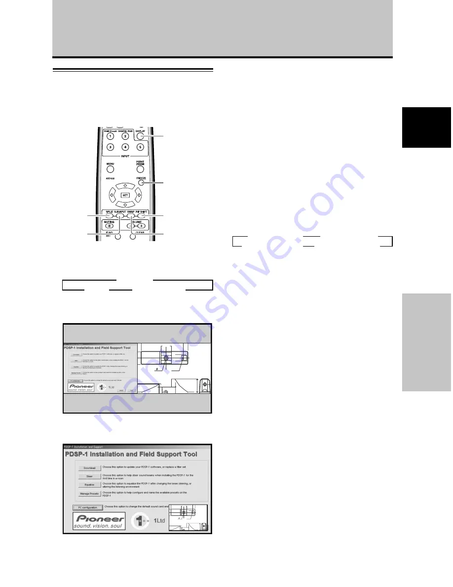
Affichage multi-écran

La fonction Multi-écran de cet écran à plasma autorise
l’affichage simultané de deux entrées. L’affichage multi-
écran comprend deux modes : Côte à côte et Image dans
image.

1

Appuyez sur la touche SPLIT de la télécommande.

À chaque pression sur la touche, l’affichage multi-
écran change dans l’ordre suivant :

1

Côte à côte

L’écran principal apparaît sur la gauche et le sous-
écran sur la droite.

66.0

22.1

R12

24

10

2

Image dans image

Le sous-écran est affiché dans un des quatre coins de
l’écran principal.

66.0

22.1

R12

24

10

2

Appuyez sur la touche SUB INPUT de la
télécommande pour sélectionner la source
d’entrée du sous-écran.

Pour permuter les entrées à l’écran principal et
au sous-écran :

Appuyez sur la touche SWAP de la télécommande.

Lorsque le mode côte à côte est sélectionné :
Les côtés droit et gauche de l’affichage permutent. Ce
qui était affiché sur l’écran principal apparaît sur le sous-
écran et vice versa.

Lorsque le mode Image dans image est sélectionné :
Ce qui était affiché sur l’écran principal apparaît en
format réduit sur le sous-écran et vice versa.

Pour changer la position du sous-écran en mode
Image dans image :

Appuyez sur la touche PIP SHIFT de la télécommande.

À chaque pression sur cette touche, la position du sous-
écran change dans l’ordre suivant :

Pour afficher l’entrée actuellement sélectionnée :

Appuyez sur la touche DISPLAY.

Si la touche 

DISPLAY 

est actionnée en mode Multi-écran,

l’écran principal et le sous-écran afficheront
respectivement leur entrée actuellement sélectionnée.

Remarques

Lorsque l’écran à plasma est utilisé pour une activité à but lucratif
ou pour la présentation d’images en public, l’emploi de la fonction
Format d’écran pour comprimer ou élargir une image peut
entraîner une violation des copyrights des détenteurs des images.

Si l’affichage multi-écran est laissé en service pendant
longtemps ou si le même affichage multi-écran est utilisé
quotidiennement de façon répétée et pendant de brèves
périodes, une image rémanente risque de se former sur l’écran.

En fonction de la source utilisée, l’image peut sembler un peu
sommaire lorsque vous utilisez le mode Côte à côte.

Le mode multi-écran sera annulé si un menu est ouvert ou si la
fonction Agrandissement partiel de l’image (POINT ZOOM) est
utilisée.

Le format d’écran ne peut pas être modifié pendant l’affichage
Multi-écran.

Le son de l’entrée sélectionnée sur l’écran principalest fourni
lorsque vous utilisez la fonction Multi-écran.

SWAP

PIP SHIFT

SUB INPUT

SPLIT

DISPLAY

FREEZE

3

 Côte à côte

Image dans image 

2

ARRÊT 

2

3

 Coin inférieur droit

3

 Coin supérieur droit

Coin inférieur gauche 

2

Coin supérieur gauche 

2

Содержание 507CMX - PDP - 50" Plasma Panel

Страница 1: ...er to the instructions written in Japanese Les caractéristiques les spécifications d alimentation les accessoires et d autres informations diffèrent d un pays à l autre Si vous vivez au Canada ou aux États Unis reportez vous aux instructions en français ou en anglais Si vous vivez au Japon reportez vous aux instructions en japonais 電源 付属品などの差異がありますので 日本国内でご購入 ご 使用の際は 本書の日本語ページをご覧ください その他の 国 地域でご購入...

Страница 2: ...ails consult your local retail dealer Français Cet appareil est conçu pour une utilisation comme moniteur d affichage d ordinateur La carte vidéo optionnelle est nécessaire si vous souhaitez regarder d autres signaux sur ce moniteur Pour plus de renseignements consultez votre revendeur 日本語 本機はパソコン用モニターとして設計されています 本機でビデオ信号を見るときは 別売りのビデオカードが必要です 詳しくは お買い求めの取り扱い店にお問い合わせください ...

Страница 3: ...u will find it useful in the future Notes on Installation Work This product is marketed assuming that it is installed by qualified personnel with enough skill and competence Always have an installation specialist or your dealer install and set up the product PIONEER cannot assume liabilities for damage caused by mistake in installation or mounting misuse modification or a natural disaster Note for...

Страница 4: ...within the product s enclosure that may be of sufficient magnitude to constitute a risk of electric shock to persons CAUTION TO PREVENT THE RISK OF ELECTRIC SHOCK DO NOT REMOVE COVER OR BACK NO USER SERVICEABLE PARTS INSIDE REFER SERVICING TO QUALIFIED SERVICE PERSONNEL CAUTION RISK OF ELECTRIC SHOCK DO NOT OPEN IMPORTANT WARNING This equipment is not waterproof To prevent a fire or shock hazard d...

Страница 5: ...particular installation If this equipment does cause harmful interference to radio or television reception which can be determined by turning the equipment off and on the user is encouraged to try to correct the interference by one or more of the following measures Reorient or relocate the receiving antenna Increase the separation between the equipment and receiver Connect the equipment into an ou...

Страница 6: ...cate the nearest Pioneer Authorized Independent Service Company or if you wish to purchase replacement parts operating instructions service manuals or accessories please call the number shown below 8 0 0 4 2 1 1 6 2 5 Please do not ship your product to Pioneer without first calling the Customer Support Division at the above listed number for assistance Pioneer Electronics USA Inc Customer Support ...

Страница 7: ...0 Changing screen size 21 Enlarging one part of the screen POINT ZOOM 22 Multiscreen display 23 Automatic power off POWER MANAGEMENT 24 PICTURE SCREEN Adjustment 25 PICTURE adjustment 25 Adjusting screen POSITION CLOCK and PHASE automatic adjust 26 Adjusting screen POSITION CLOCK and PHASE manual adjust 27 Other Operations 29 Setting the ORBITER 29 Setting the SOFT FOCUS 30 Energy saving settings ...

Страница 8: ...ls are different on INPUT1 and INPUT2 1 Aspect ratio and screen size appearance will differ depending on input signal Free Installation Configuration Broader installation possibilities with thinner lighter high endurance design PDP 507CMX While producing a large 50 screen image the display is only 99 mm thick and weighs in at only 35 5 kg PDP 607CMX While producing a large 60 screen image the disp...

Страница 9: ...ll the necessary points regarding installation of the Plasma Display and connections to a wide variety of components The section System Settings starting on page 17 covers the on screen settings necessary for correct operation of the Plasma Display with its connected components Depending on the connections made this section may or may not be necessary The remainder of the sections in this manual i...

Страница 10: ...ose found on the remote control unit the commands can be performed on the main unit as well The following illustrations are an example of the actual operations used for the section PICTURE adjustment The examples are provided to allow you to confirm whether the operation is performed correctly or not Before Proceeding Note The screen images depicted in these Operating Instructions should be consid...

Страница 11: ...hat the following accessories were supplied 1 Power cord 2 m 6 6 feet 2 Remote control unit 3 AA R6 batteries x 2 4 Cleaning cloth for screen 5 Speed clamps x 3 6 Bead bands x 3 Before Proceeding 7 Ferrite cores x 3 for audio cables These Operating Instructions Warranty ...

Страница 12: ...andby mode The indicator lights red page 19 When flashing the indicator is used to indicate error messages page 40 4 Handles Operation panel on the main unit 5 STANDBY ON button Press to put the display in operation or standby mode page 19 6 MENU button Press to open and close the on screen menu pages 17 to 36 7 DISPLAY SET button Use to confirm onscreen menu selections and to change settings page...

Страница 13: ...mputer signal input automatically sets the POSITION CLOCK and PHASE to optimum values page 26 STANDBY ON button Press to put the unit in operation or standby mode page 19 DISPLAY button Press to view the unit s current input and setup mode page 20 POINT ZOOM button Use to select and enlarge one part of the screen page 22 FREEZE button When memo screen function is enabled a still image is displayed...

Страница 14: ...anel of the main unit The remote control unit is operable up to 7 m from the unit and within a 30 angle on each side of the sensor Inserting the batteries in the remote control unit Designated batteries Please use size AA R6 or AA LR6 CAUTION Do not use batteries other than those designated and do not mix old and new batteries together since rupture or leakage may result leading to danger of fire ...

Страница 15: ...nnect the audio output jack of components connected to INPUT1 to this unit page 14 Connection panel PDP 507CMX The connection panel is provided with two video input terminals and one video output terminal Audio input output and speaker output terminals are also provided For instructions regarding connections consult the pages noted in parentheses by each item 7 AUDIO INPUT2 Stereo mini jack Use to...

Страница 16: ...provided with two video input terminals and one video output terminal Audio input output and speaker output terminals are also provided For instructions regarding connections consult the pages noted in parentheses by each item 6 AUDIO INPUT1 Stereo mini jack Use to obtain sound when INPUT1 is selected Connect the audio output jack of components connected to INPUT1 to this unit page 14 7 AUDIO INPU...

Страница 17: ...e unit to fall causing injuries or damage Wall mount installation of the unit This unit has been designed with bolt holes for wall mount installation etc The installation holes provided are shown in the accompanying illustration Be sure to attach in 4 or more locations above and below left and right of the center line Use bolts that are long enough to be inserted 12 mm 1 2 in to 18 mm 11 16 in int...

Страница 18: ... in 12 mm to 14 mm 1 2 in to 9 16 in Side view diagram Installation and Connections b hole Center line b hole b hole b hole Center line Rear view diagram PDP 507CMX a hole a hole Air vents fan b hole Center line b hole b hole b hole Center line Rear view diagram PDP 607CMX a hole a hole Air vents fan a hole a hole a hole a hole Only for speaker unit ...

Страница 19: ... necessary For details please read your PC s instruction manual or consult the maker or nearest dealer of your computer NOTICE INPUT1 supports Microsoft Plug Play VESA DDC 1 2B components See Appendix 2 1 2 page 45 when making connections to INPUT1 See Appendix 1 pages 42 to 43 for information regarding signals and display formats supported by INPUT1 To an external monitor When connecting to ANALO...

Страница 20: ...nnections to the audio inputs on this unit This unit features two audio inputs and one audio output The following chart shows the video inputs and the corresponding audio input terminals Twist exposed wire strands together Push tab to the open position and insert the wire Then close tab firmly to secure the wire in place INPUT1 INPUT2 Audio input jacks Sound output Stereo mini jack L R Stereo mini...

Страница 21: ...isconnect the power cord from its wall outlet For the Plasma Display use a three core power cord with a ground terminal Always be sure to connect the power cord to a three pronged grounded outlet and make sure that the cord is properly grounded If you use a power source converter plug use an outlet with a ground terminal and screw down the ground line NO Do not use a power supply voltage other tha...

Страница 22: ... clamps to the main unit Use the holes marked with the sign as needed Connect the speed clamps using the 4 holes marked with below depending on the situation PDP 507CMX PDP 607CMX 1 Organize cables together using the provided speed clamps Insert 1 into an appropriate hole on the rear of the unit then snap 2 into the back of 1 to fix the clamp Speed clamps are designed to be difficult to undo once ...

Страница 23: ... SPLIT FREEZE AUTO SETUP MODE AUTO FUNCTION PIP DETECT PICTURE STANDARD INACTIVE OFF ACTIVE ENGLISH OFF 5 Use the 5 buttons to select LANGUAGE then press the SET button LANGUAGE ENGLISH SET SET EXIT MENU 6 Use the 2 3 buttons to select the desired language Each time the 2 3 buttons are pressed the language alternates between those available in the following order LANGUAGE ENGLISH SET SET EXIT MENU...

Страница 24: ...nals are detected automatically in accordance with the Computer signal compatibility table pages 42 to 44 Others Selectable resolutions are displayed 5 Press the SET button The setting is stored in memory and the screen returns to that shown in step 3 6 When the setup is completed press the MENU button to exit the menu screen Note Make SIGNAL FORMAT setting for each input INPUT1 and INPUT2 MENU 5 ...

Страница 25: ... displayed FULL FH 86 7kHz FV 88 5Hz POL H POL V UNSUPPORTED SIGNAL CAUTION INPUT1 4 Use VOLUME buttons to adjust the sound volume If no audio connections are made to this unit this step is not necessary 5 When viewing is finished press the STANDBY ON button to put the unit in standby mode 6 Set the rear panel MAIN POWER switch to OFF The STANDBY ON indicator may continue to light for a short whil...

Страница 26: ...s the VOLUME buttons Press the or button to respectively decrease and increase the volume of sound from the speakers 10 VOLUME Muting the sound MUTING Press the MUTING button on the remote control unit Press the MUTING button again to restore the sound Press VOLUME or VOLUME to adjust the volume at a desired level STANDBY ON MENU DISPLAY SET VOL INPUT SCREEN SIZE DISPLAY SET STANDBY ON MENU DISPLA...

Страница 27: ...s much as possible without altering the aspect ratio of the input signal A 3 FULL The display is presented with a widescreen aspect ratio of 16 9 and fills the entire screen A The screen size changes each time the SCREEN SIZE button is pressed as follows or Consult the Computer signal compatibility table pages 42 to 44 for information regarding screen sizes supported by each signal format Notes Wh...

Страница 28: ...a subscreen Each time the POINT ZOOM button is pressed the zoom ratio alternates in the following order LEVEL1 x1 LEVEL2 x1 5 LEVEL3 x2 LEVEL4 x3 2 Using the 5 2 3 buttons move the screen to the desired part of the image 10 84 3 50 10 22 1 R12 24 Notes During use of the POINT ZOOM function the screen size cannot be changed When using the Plasma Display in a profit making activity or when exhibitin...

Страница 29: ...change the position of the subscreen in picture in picture mode Press the remote control unit s PIP SHIFT button Each time the button is pressed the position of the subscreen moves in the following order To display the currently selected input Press the DISPLAY button If the DISPLAY button is pressed while in multiscreen mode the main screen and sub screen will each be displayed with its currently...

Страница 30: ...c signal ON If a sync signal is not detected a warning message is first displayed for 8 seconds after which the display automatically enters the standby mode and the STANDBY ON indicator flashes green If a sync signal is input again later the Plasma Display automatically returns to normal operating mode 1 1 Except when input signal is G ON SYNC or composite SYNC 4 When the setup is finished press ...

Страница 31: ...et PICTURE mode settings to the default If settings have been adjusted excessively or the picture on the screen no longer appears natural it may prove more beneficial to reset the PICTURE mode to default settings instead of trying to make adjustments under already adjusted conditions 1 In step 2 in the previous procedure use the 5 buttons to select PICTURE RESET then press the SET button SET SET E...

Страница 32: ...TO SETUP MODE to INACTIVE and use the manual adjustment methods explained in the following section Adjusting screen POSITION CLOCK and PHASE manual adjust AUTO SET UP When the automatic setup mode is selected the unit will automatically be adjusted to the optimum image settings whenever the power is turned on the input source is changed or the type of input signal is changed MENU 5 SET 2 3 1 Press...

Страница 33: ...U button to return to the normal screen image Note Optimum settings may not be possible for low luminance and certain other signals In such cases set the AUTO SETUP MODE to INACTIVE and use the manual adjustment methods explained in the following section Adjusting screen POSITION CLOCK and PHASE manual adjust 3 INACTIVE ACTIVE 2 1 Press the MENU button to display the menu screen SCREEN SETUP OPTIO...

Страница 34: ...ker of screen letters or color misalignment This setting adjusts the phase of the internal clock signal adjusted by the CLOCK setting Notes The CLOCK and PHASE adjustment items are supported only for INPUT1 When the CLOCK frequency is changed the POSITION command s horizontal H option may require readjustment If the adjustment items in the SCREEN mode are adjusted excessively the picture may not b...

Страница 35: ...R SETTING SCREEN MGT SPLIT FREEZE AUTO SETUP MODE AUTO FUNCTION PIP DETECT PICTURE STANDARD INACTIVE OFF ACTIVE ENGLISH OFF 4 Use the 5 buttons to select ORBITER CHANGE SET EXIT MENU SCREEN MANAGEMENT ORBITER SOFT FOCUS OFF OFF 5 Press the 2 3 buttons to activate the setting The factory default setting is OFF Each time the button is pressed the setting alternates as follows OFF The ORBITER is not ...

Страница 36: ...ETUP OPTION LANGUAGE ENERGY SAVE TIMER SETTING SCREEN MGT SPLIT FREEZE AUTO SETUP MODE AUTO FUNCTION PIP DETECT PICTURE STANDARD INACTIVE OFF ACTIVE ENGLISH OFF 4 Use the 5 buttons to select SOFT FOCUS CHANGE SET EXIT MENU SCREEN MANAGEMENT ORBITER SOFT FOCUS OFF OFF 5 Press the 2 3 buttons to activate the setting The factory default setting is OFF Each time the button is pressed the setting alter...

Страница 37: ...pressed the setting changes as follows STANDARD1 Normal image brightness STANDARD2 Brightness is controlled in accordance with input signal to produce easily viewed image PDP 507CMX only AUTO Brightness is set automatically in response to ambient lighting conditions so as to produce optimum image appearance PDP 507CMX only MODE1 Brightness is controlled in accordance with input signal but power co...

Страница 38: ...NCTION is disabled INPUT1 When a signal is detected at INPUT1 the input source automatically switches to INPUT1 After the AUTO FUNCTION mode has caused the input to switch if the input signal is no longer detected the input source reverts to the one selected before operation of the AUTO FUNCTION mode If the input changes when the unit is in AUTO FUNCTION mode pressing the INPUT button to select a ...

Страница 39: ...se to set to daylight savings time ON Displays time as present time 1 hour OFF Disables DAYLIGHT SAVING TIME mode Week Set current day of the week Hour Minute Sets to current time 6 When finished with the setting use the 5 buttons to select RETURN then press the SET button to return to the TIMER SETTING menu Note The TIMER SETTING setting affects all input sources MENU 5 SET 2 3 1 Press the MENU b...

Страница 40: ...ICTURE STANDARD INACTIVE OFF ACTIVE ENGLISH OFF 4 Use the 5 buttons to select PROGRAM REPEAT CHANGE SET EXIT MENU TIMER SETTING PROGRAM REPEAT RETURN OFF PRESENT TIME 5 Press the 2 3 buttons to activate the setting The factory default setting is OFF Each time the button is pressed the setting alternates as follows 6 When finished with the setting use the 5 buttons to select RETURN then press the S...

Страница 41: ...VE OFF ACTIVE ENGLISH OFF 3 Use the 5 buttons to select PIP DETECT MENU INPUT1 CHANGE SET EXIT MENU SCREEN SETUP OPTION LANGUAGE ENERGY SAVE TIMER SETTING SCREEN MGT SPLIT FREEZE AUTO SETUP MODE AUTO FUNCTION PIP DETECT PICTURE STANDARD INACTIVE OFF ACTIVE ENGLISH OFF 4 Press the SET button to activate the setting The factory default setting is ACTIVE Each time the button is pressed the setting al...

Страница 42: ... SET button to activate the setting The factory default setting is OFF Each time the button is pressed the setting alternates as follows OFF The still picture displayed at the time the FREEZE button was pressed is displayed as a single fullscreen image S BY S When the FREEZE button is pressed the freeze frame image will be displayed in the side by side subscreen PIP When the FREEZE button is press...

Страница 43: ...r wringing the cloth thoroughly wipe the component and then dry it with a dry soft cloth Cleaning the screen After dusting wipe the screen gently using the supplied cleaning cloth or another soft cloth cotton flannel etc Do not use tissue or a rough cloth As the surface of the screen is easily scratched do not rub it or hit it with a hard object If you clean the surface of the screen with a wet cl...

Страница 44: ... connections and other settings Turn off main power wait for 1 to 2 minutes then try turning power on again If problem persists remove power plug from its outlet and consult a Pioneer service center or your dealer Troubleshooting What may at first seem to be an malfunction may be remedied with a quick check Please check to see if a warning is displayed on the screen If displayed refer to the table...

Страница 45: ...Plasma Display panel Not a malfunction Fan speed changes automatically in accordance with ambient conditions Not a malfunction The ON indicator may not light in some cases depending on the settings performed by the installer Consult with your installation technician Problem Possible Solution No power Unit cannot be operated Remote control does not operate Picture is cut off Strange color light col...

Страница 46: ... a malfunction Concerning infrared light In principle the Plasma Display radiates infrared light Depending on the environment in which the monitor is installed and used infrared remote control units for other nearby appliances may fail to operate properly or noise may be heard in wireless headphones In such cases move the affected appliance to a location where its infrared sensor is not affected E...

Страница 47: ...ormation Input output Video INPUT1 Input Mini D sub 15 pin socket connector RGB signal G ON SYNC compatible RGB 0 7 Vp p 75 Ω no sync HD VS VD TTL level positive and negative polarity 2 2 kΩ G ON SYNC 1 Vp p 75 Ω negative sync Compatible with Microsoft Plug Play VESA DDC 1 2B Output Mini D sub 15 pin socket connector 75 Ω with buffer INPUT2 Input DVI D 24 pin connector Digital RGB signal DVI compl...

Страница 48: ...C PC 9800 NEC PC 9800 Apple Macintosh 13 I O DATA I O DATA I O DATA I O DATA I O DATA Apple Macintosh 16 Work station SGI indicates Apple Macintosh 19 I O DATA I O DATA I O DATA CVT PC Apple Macintosh 21 Sun Microsystems LO Sun Microsystems HI 1365x768 1365x768 1365x768 1365x768 1365x768 1365x768 1365x768 1365x768 1365x768 1365x768 1365x768 1365x768 1365x768 1365x768 1365x768 1365x768 640x480 720x...

Страница 49: ...n SGI Work station EWS4800 Work station EWS4800 Work station HP Work station SUN I O DATA CVT CVT Optimal picture Adjustment of picture position refresh rate phase etc may be necessary Picture will be enlarged but some fine detail will be hard to see Simple reproduction Fine detail will not be reproduced Appendix 1 2 2 INPUT2 Resolution Dot x Line Vertical DOT BY DOT FULL Remarks Screen size Dot x...

Страница 50: ... kHz 64 0 kHz 64 6 kHz 75 1 kHz 78 1 kHz 81 1 kHz 80 0 kHz 91 1 kHz 65 3 kHz 65 3 kHz 56 2 kHz 57 5 kHz 75 0 kHz 74 0 kHz 1024x768 1280x768 1360x768 1024x768 1024x768 1024x768 960x768 1024x768 1024x768 1365x768 1365x768 1365x768 1365x768 1365x768 1365x768 1365x768 1365x768 1365x768 1365x768 1365x768 1365x768 1365x768 1365x768 1365x768 1365x768 Work station SGI I O DATA I O DATA Work station SUN Wo...

Страница 51: ...ta1 T M D S Data1 3 Shield NC No connection NC No connection 5V Power GND Hot Plug Detect T M D S Data0 T M D S Data0 T M D S Data0 5 Shield NC No connection NC No connection T M D S Clock Shield T M D S Clock T M D S Clock Pin No 5 1 15 11 6 10 Appendix 2 INPUT1 2 pin assignments Appendix 2 1 2 INPUT1 Mini D sub 15 pin female connector pin allocation Input Output 1 2 3 4 5 6 7 8 9 10 11 12 13 14 ...

Страница 52: ...tes a 1280 dot x 768 line resolution SXGA General term for Super eXtended Graphics Array Generally this indicates a 1280 dot x 1024 line resolution SXGA General term for Super eXtended Graphics Array plus Generally this indicates a 1400 dot x 1050 line resolution DVI General term for Digital Visual Interface An interface standard proposed by the Digital Display Working Group DDWG for digital displ...

Страница 53: ...le dans les mois ou les années qui suivent Remarques sur l installation Ce produit est vendu en assumant qu il sera installé par un personnel suffisamment expérimenté et qualifié Faites toujours réaliser le montage et l installation par un spécialiste ou par votre revendeur PIONEER ne peut être tenu responsable pour tout dommage causé par une erreur d installation ou de montage une mauvaise utilis...

Страница 54: ...ymbole de l éclair placé dans un triangle équilatéral a pour but d attirer l attention de l utilisateur sur la présence à l intérieur du coffret de l appareil de tensions dangereuses non isolées d une grandeur suffisante pour représenter un risque d électrocution pour les êtres humains IMPORTANT ATTENTION POUR ÉVITER TOUT RISQUE D ÉLECTROCUTION NE PAS ENLEVER LE COUVERCLE NI LE PANNEAU ARRIÈRE AUC...

Страница 55: ...interférences à l aide de l une ou plusieurs mesures suivantes Réorientez ou déplacez l antenne réceptrice Augmentez l espace entre l appareil est le récepteur Connectez l appareil sur une prise secteur appartenant à un circuit différent de celui sur lequel le récepteur est connecté Consultez votre revendeur ou un technicien radio télévision expérimenté ATTENTION Ce produit satisfait aux règlement...

Страница 56: ...Centre de Service Autorisé Pioneer le plus près de chez vous Vous pouvez aussi contacter le Service à la clientèle de Pioneer Pioneer Électroniques du Canada Inc Service à la clientèle 300 Allstate Parkway Markham Ontario L3R OP2 905 479 4411 1 877 283 5901 Pour obtenir des renseignements sur la garantie veuillez vous reporter au feuillet sur la garantie restreinte qui accompagne le produit S021_E...

Страница 57: ... de l écran 21 Agrandissement partiel de l image POINT ZOOM 22 Affichage multi écran 23 Mise hors tension automatique GESTION D ALIM 24 Réglages de l IMAGE et de l ÉCRAN 25 Réglage de l IMAGE 25 Réglage de la POSITION de l écran de l HORLOGE et de la PHASE Réglage automatique 26 Réglage de la POSITION de l écran de l HORLOGE et de la PHASE Réglage manuel 27 Autres démarches 29 Réglage de l orbiteu...

Страница 58: ...rennent POINT PAR POINT 4 3 et PLEIN ÉCRAN 1 Les signaux pris en compte sont différents à INPUT1 et à INPUT2 1 L aspect du rapport largeur hauteur et de la taille d écran varie selon le signal d entrée Configuration d installation plus libre Possibilités élargies d installation par un solide design plus mince et plus léger PDP 507CMX Bien qu il fournisse une image de 50 pouces cet écran n a que 99...

Страница 59: ... couvre tous les aspects de l installation de l écran à plasma et des raccordements à effectuer avec les autres appareils de l installation La section Paramétrages du système qui débute à la page 17 traite des réglages sur écran nécessaires pour que l écran à plasma fonctionne correctement avec les autres composants raccordés En fonction des raccordements réalisés il peut être utile de lire cette ...

Страница 60: ...ma et sur la télécommande celles de l appareil principal peuvent être utilisées également Les illustrations suivantes sont un exemple des démarches réelles utilisées pour la section Réglage de l IMAGE Les exemples sont fournis pour vous permettre de vérifier si les démarches se déroulent correctement ou non Avant de commencer Remarque Les images d écran illustrées dans ce manuel ne sont présentées...

Страница 61: ...is Assurez vous que les accessoires suivants font partie de la fourniture 1 Cordon d alimentation 2 m 2 Télécommande 3 2 piles AA R6 4 Chiffon de nettoyage pour l écran 5 3 colliers rapides 6 3 serre câble 7 3 noyaux en ferrite pour câbles audio Le présent mode d emploi Carte de garantie ...

Страница 62: ...ique la présence de messages d erreur page 40 4 Poignées Panneau de commande de l écran à plasma 5 Touche STANDBY ON veille marche Appuyez sur cette touche pour mettre l écran en service ou en veille page 19 6 Touche MENU Appuyez sur cette touche pour ouvrir ou fermer les menus s affichant sur l écran pages 17 à 36 7 Touche DISPLAY SET écran validation Elle sert à valider les sélections sur les me...

Страница 63: ...timales page 26 Touche STANDBY ON Appuyez sur cette touche pour mettre l écran en service ou en veille page 19 Touche DISPLAY Appuyez sur cette touche pour afficher le nom de l entrée et de mode de fonctionnement actuels page 20 Touche POINT ZOOM Utilisez cette touche pour choisir et agrandir une partie de l écran page 22 Touche FREEZE Quand la fonction d écran de mémo est validée une image fixe e...

Страница 64: ...tilisez des piles de format AA R6 ou AA LR6 ATTENTION N utilisez pas de piles autres que celles qui sont désignées et ne mélangez pas des piles usées et des neuves car une rupture ou une fuite d électrolyte pourrait en résulter ce qui présenterait un risque d incendie de blessure ou de contamination Lors de la mise en place des piles dans la télécommande insérez les en faisant correspondre leurs p...

Страница 65: ...r des sons appliqués sur INPUT1 Branchez sur cette prise la sortie son de l appareil relié à INPUT1 page 14 7 AUDIO INPUT2 Mini prise stéréo Utilisez cette prise pour disposer des sons appliqués sur INPUT2 Branchez sur cette prise la sortie son de l appareil relié à INPUT2 page 14 8 ANALOG RGB OUT INPUT1 mini prise D sub à 15 broches Utilisez la prise ANALOG RGB OUT INPUT1 pour appliquer le signal...

Страница 66: ...er des sons appliqués sur INPUT1 Branchez sur cette prise la sortie son de l appareil relié à INPUT1 page 14 7 AUDIO INPUT2 Mini prise stéréo Utilisez cette prise pour disposer des sons appliqués sur INPUT2 Branchez sur cette prise la sortie son de l appareil relié à INPUT2 page 14 8 ANALOG RGB OUT INPUT1 mini prise D sub à 15 broches Utilisez la prise ANALOG RGB OUT INPUT1 pour appliquer le signa...

Страница 67: ...il des blessures et des dégâts Accrochage de l écran à plasma à un mur L écran à plasma possède des perçages destinés à permettre sa fixation sur un mur etc Les perçages prévus sont indiqués sur l illustration fournie L écran à plasma doit être maintenu en 4 points minimum placés au dessus et au dessous de l axe horizontal et à droite et à gauche de l axe vertical Dans le cas des perçages a et b u...

Страница 68: ...12 mm à 18 mm 12 mm à 14 mm Vue de côté Perçage b Axe Perçage b Perçage b Perçage b Axe Vue arrière PDP 507CMX Perçage a Perçage a Ouïes d aération ventilateur Perçage a Perçage a Perçage a Perçage a Perçage b Axe Perçage b Perçage b Perçage b Axe Vue arrière PDP 607CMX Perçage a Perçage a Ouïes d aération ventilateur Uniquement pour haut parleur ...

Страница 69: ...e revendeur NOTICE La prise INPUT1 prend en compte les composants à approche Plug Play VESA DDC 1 2B de Microsoft Consultez le Supplément 2 1 2 page 45 lors de connexions sur INPUT1 Consultez le Supplément 1 pages 42 à 43 pour des informations sur les signaux et les formats d affichage pris en compte par INPUT1 Installation et raccordements Pour le raccordement à ANALOG RGB OUT INPUT1 ANALOG RGB O...

Страница 70: ... cet écran à plasma Cet écran à plasma est doté de deux entrées audio et d une sortie audio Le tableau qui suit donne pour chaque entrée vidéo les entrées audio correspondantes Torsadez les brins mis à nu Soulevez la languette puis introduisez le conducteur Abaissez la languette pour maintenir le conducteur en place Raccordement audio pour un appareil ordinateur relié à INPUT1 AUDIO AUDIO INPUT1 A...

Страница 71: ...r d alimentation général de l appareil sur arrêt et débranchez le cordon d alimentation de sa prise de sortie secteur murale Pour l écran plasma utilisez un cordon d alimentation à trois broches muni d une borne de terre Veillez à ce que la prise possède une broche de mise à la terre et qu elle soit convenablement câblée En cas d utilisation d un adaptateur le conducteur de masse doit tout de même...

Страница 72: ...olliers rapides à l écran à plasma Utilisez les trous indiqués par le signe selon les besoins Engagez les colliers rapides dans les trous 4 repérés par sur l illustration ci dessous PDP 507CMX PDP 607CMX Vue de l arrière de l écran 1 Groupez les câbles en utilisant les colliers rapides fournis Introduisez la partie 1 dans un des perçages à l arrière de l écran à plas ma puis insérez 2 à l arrière ...

Страница 73: ...TIMER SETTING SCREEN MGT SPLIT FREEZE AUTO SETUP MODE AUTO FUNCTION PIP DETECT PICTURE STANDARD INACTIVE OFF ACTIVE ENGLISH OFF 5 Utilisez les touches 5 pour sélectionner LANGUAGE puis appuyez sur la touche SET LANGUAGE ENGLISH SET SET EXIT MENU 6 Utilisez les touches 2 3 pour sélectionner la langue souhaitée A chaque pression sur les touches 2 3 les langues disponibles changent dans l ordre suiva...

Страница 74: ...ignal d entrée VALIDER SET SORTIE MENU TYPE DE SIGNAL AUTO A chaque pression sur les boutons 2 3 la sélection alterne comme suit AUTO Les signaux sont automatiquement détectés en accord avec le tableau des comptabilités de signal d ordinateur pages 42 à 44 Autres Les résolutions utilisables sont affichées 5 Appuyez sur la touche SET Le réglage est mémorisé et l écran repasse à celui illustré à l é...

Страница 75: ...affiché POL H POL V PLEIN ÉCRAN SIGNAL NON RECONNU FH 86 7kHz ATTENTION FV 88 5Hz ENTRÉE1 4 Utilisez les touches VOLUME pour ajuster le volume sonore Si aucune signal sonore n est appliqué à l écran à plasma cette opération est inutile 5 Lorsque vous avez fini de regarder les images appuyez sur la touche STANDBY ON pour placer l écran à plasma en veille 6 Réglez l interrupteur MAIN POWER du pannea...

Страница 76: ... POINT PAR POINT 640X 480 FH 31 5kHz FV 60 0Hz POL H NEGA POL V POSI Remarque Il se peut que les fréquences de rafraîchissement affichées soient légèrement différentes des valeurs réelles STANDBY ON MENU DISPLAY SET VOL INPUT SCREEN SIZE VOL VOLUME Télécommande Panneau de commande de l écran à plasma MUTING STANDBY ON MENU DISPLAY SET VOL INPUT SCREEN SIZE DISPLAY SET DISPLAY Panneau de commande d...

Страница 77: ...sible mais le format n est pas modifi A 3 PLEIN ÉCRAN L image a le format 16 9 et remplit l écran A Le format d image change comme suit chaque fois que la touche SCREEN SIZE est actionnée ou Consultez le Tableau des compatibilités de signal d ordinateur pages 42 à 44 pour des renseignements sur les tailles d écran supportées par chaque format de signal Remarques Si vous utilisez un format grand éc...

Страница 78: ...Si le signal d entrée change si la page de menu est affichée et que l entrée est changée ou si le mode multi écran est sélectionné la fonction Agrandissement partiel de l image POINT ZOOM sera annulée Fonctionnement Agrandissement partiel de l image POINT ZOOM Cet écran à plasma autorise un agrandissement de l image affichée Lorsque l image est agrandie la zone de sa vision peut être déplacée sur ...

Страница 79: ...ommande À chaque pression sur cette touche la position du sous écran change dans l ordre suivant Pour afficher l entrée actuellement sélectionnée Appuyez sur la touche DISPLAY Si la touche DISPLAY est actionnée en mode Multi écran l écran principal et le sous écran afficheront respectivement leur entrée actuellement sélectionnée Remarques Lorsque l écran à plasma est utilisé pour une activité à bu...

Страница 80: ...r quitter la page de menu Remarque La fonction GESTION D ALIM doit être réglée individuellement pour chaque entrée INPUT1 et INPUT2 Pour revenir au mode de fonctionnement Pour repasser au mode de fonctionnement normal depuis le mode Veille de la fonction GESTION D ALIM faites fonctionner votre ordinateur ou appuyez sur la touche INPUT Fonctionnement 3 ARRÊT MARCHE 2 Mise hors tension automatique G...

Страница 81: ... l image dans le sens vertical Pour rétablir les valeurs par défaut des paramètres de l option IMAGE Si les réglages effectués ne vous conviennent pas il peut être souhaitable de rétablir les valeurs par défaut des différents paramètres de l option IMAGE plutôt que de continuer à modifier les réglages 1 Au cours de l opération 2 ci dessus utilisez les touches 5 pour choisir l option RÉINIT IMAGE p...

Страница 82: ...rtains autres types Dans ces cas réglez le mode RÉGLAGE AUTO sur INACTIF et utilisez les méthodes de réglage manuel expliquées dans la section suivante Réglage de la POSITION de l écran de l HORLOGE et de la PHASE Réglage manuel Lorsque le mode de paramétrage automatique est sélectionné l appareil sera automatiquement ajusté aux paramètres idéaux lors de sa mise sous tension lorsque la source d en...

Страница 83: ...r à l image de l écran normal Remarque Il se peut que les réglages optimaux ne soient pas obtenus avec des signaux à faible luminance ou certains autres types Dans ces cas réglez le mode RÉGLAGE AUTO sur INACTIF et utilisez les méthodes de réglage manuel expliquées dans la section suivante Réglage de la POSITION de l écran de l HORLOGE et de la PHASE Réglage manuel 3 INACTIF ACTIF 2 1 Appuyez sur ...

Страница 84: ... scintillement et des erreurs de couleur Ce réglage agit sur la phase du signal de l horloge interne dont la fréquence a été réglée au moyen du paramètre HORLOGE Remarques Les paramètres de réglage HORLOGE et PHASE sont pris en compte uniquement pour ENTRÉE1 Si la fréquence HORLOGE est changée il se peut que l option H de la commande POSITION doive être retouchée Si les paramètres de l option ÉCRA...

Страница 85: ...GE MENU ENTRÉE1 ENTRÉE SORTIE LANGUAGE TIMER MODE AUTO ÉCON ÉNERGIE PROTECT ÉCRAN GEL MULTI IMAGE RÉGLAGE AUTO DÉTECTION PIP 4 Utilisez les touches 5 pour sélectionner ORBITER CHANGER SET SORTIE MENU ANTI MARQUAGE ÉCRAN ORBITER FOCUS LEGER ARRÊT ARRÊT 5 Appuyez sur les touches 2 3 pour valider le réglage Le réglage par défaut effectué en usine est ARRÊT À chaque pression sur la touche le réglage c...

Страница 86: ...IS ARRÊT ÉCRAN SETUP OPTION IMAGE MENU ENTRÉE1 ENTRÉE SORTIE LANGUAGE TIMER MODE AUTO ÉCON ÉNERGIE PROTECT ÉCRAN GEL MULTI IMAGE RÉGLAGE AUTO DÉTECTION PIP 4 Utilisez les touches 5 pour sélectionner FOCUS LEGER SET MENU CHANGER SORTIE ANTI MARQUAGE ÉCRAN ORBITER FOCUS LEGER ARRÊT ARRÊT 5 Appuyez sur les touches 2 3 pour valider le réglage Le réglage par défaut effectué en usine est ARRÊT À chaque ...

Страница 87: ...STANDARD1 Luminosité d image normale STANDARD2 La luminosité est contrôlée en fonction du signal d entrée afin d optimiser la vision de l image PDP 507CMX seulement AUTO La luminosité se règle automatiquement en fonction des conditions de l éclairage ambiant de manière à produire des images optimales PDP 507CMX seulement MODE1 La luminosité est ajustée en fonction du signal d entrée mais la consom...

Страница 88: ... chaque pression sur la touche SET la fonction du sélecteur permute comme suit ARRÊT Le paramètre MODE AUTO est désactivé ENTRÉE1 Lorsqu un signal est détecté à INPUT1 la source d entrée passe automatiquement à ENTRÉE1 Après que la fonction MODE AUTO a provoqué le changement de l entrée la source d entrée repassera à celle qui était sélectionnée avant l action de la fonction MODE AUTO si le signal...

Страница 89: ...GE MENU ENTRÉE1 ENTRÉE SORTIE ÉCON ÉNERGIE PROTECT ÉCRAN GEL MULTI IMAGE RÉGLAGE AUTO DÉTECTION PIP 4 Utilisez les touches 5 pour sélectionner HORLOGE puis appuyez sur la touche SET ENTRÉE SET SORTIE MENU TIMER PROG REPETITION RETOUR ARRÊT HORLOGE 5 Utilisez les touches 2 3 5 pour ajuster chaque rubrique du menu CHANGER SET SORTIE MENU LUNDI 12 00 00 REGLAGE RETOUR HORLOGE ARRÊT HEURE D ÉTÉ HEURE ...

Страница 90: ...TION PIP 4 Utilisez les touches 5 pour sélectionner PROG REPETITION SET MENU CHANGER SORTIE TIMER PROG REPETITION RETOUR ARRÊT HORLOGE 5 Appuyez sur les touches 2 3 pour valider le réglage Le réglage par défaut effectué en usine est ARRÊT À chaque pression sur la touche le réglage change comme suit 6 Quand les réglages sont terminés utilisez les touches 5 pour sélectionner RETOUR puis appuyez sur ...

Страница 91: ...ON IMAGE MENU ENTRÉE1 ENTRÉE SORTIE 3 Utilisez les touches 5 pour sélectionner DÉTECTION PIP SET MENU LANGUAGE TIMER MODE AUTO STANDARD INACTIF ARRÊT ACTIF FRANÇAIS ARRÊT ÉCRAN SETUP OPTION IMAGE MENU ENTRÉE1 CHANGER SORTIE ÉCON ÉNERGIE PROTECT ÉCRAN GEL MULTI IMAGE RÉGLAGE AUTO DÉTECTION PIP 4 Appuyez sur la touche SET pour valider le réglage Le réglage par défaut effectué en usine est ACTIF À ch...

Страница 92: ...pour valider le réglage Le réglage par défaut effectué en usine est ARRÊT À chaque pression sur la touche le réglage change comme suit ARRÊT L image fixe affichée au moment où la touche FREEZE a été actionné est affichée comme image simple sur la totalité de l écran S BY S Quand la touche FREEZE est actionnée une image gelée est affichée sur le sous écran Côte à côte PIP Quand la touche FREEZE est...

Страница 93: ...uyez ensuite la surface avec un chiffon sec Nettoyage de la surface de l écran Après avoir épousseté l écran frottez le délicatement avec le chiffon de nettoyage fourni ou un autre linge doux coton flanelle etc N utilisez pas de mouchoir en papier ni de chiffon rugueux La surface de l écran peut facilement être rayée ne frottez aucun objet dur sur cette surface Si vous nettoyez la surface de l écr...

Страница 94: ...ux d entrée les raccordements et les autres réglages Coupez l alimentation principale attendez 1 à 2 minutes et remettez l appareil sous tension Si la difficulté subsiste retirez la fiche d alimentation hors de la prise secteur et consultez un centre de service ou un concessionnaire Pioneer Informations complémentaires Guide de dépannage Une erreur de commande peut parfois être interprétée comme u...

Страница 95: ...t il compatible pages 42 à 44 Les réglages IMAGE sont ils corrects page 25 Anomalies Remèdes possibles Anomalies générales Anomalies qui n en sont pas L image a un format réduit Les caractères affichés sont déformés Un son aigu est parfois émis par l écran à plasma Les portions lumineuses de l image semblent manquer d intensité Les taches ou du bruit se forment sur l écran Des rayures se forment s...

Страница 96: ...frarouge Selon l environnement dans lequel l écran est installé et utilisé les unités à commande par infrarouge d autres équipements voisins risquent de ne pas fonctionner correctement et des parasites peuvent être produits dans les écouteurs sans fil Dans ce cas déplacez l équipement à un endroit où son capteur à infrarouge ne sera pas affecté Interférence électromagnétique Cet appareil respecte ...

Страница 97: ...le Signal RVB Compatible G ON SYNC RVB 0 7 Vcc 75 Ohms pas de synchro HD VS VD Niveau TTL polarités positive et négative 2 2 kOhms G ON SYNC 1 Vcc 75 Ohms synchro négative Compatibilité Microsoft Plug Play VESA DDC 1 2B Sortie Mini D sub 15 broches connecteur femelle 75 Ohms avec tampon INPUT2 Entrée Connecteur DVI D à 24 broche Signal RVB numérique DVI conforme au signal TMDS Compatibilité Micros...

Страница 98: ...stems HI 1365x768 1365x768 1365x768 1365x768 1365x768 1365x768 1365x768 1365x768 1365x768 1365x768 1365x768 1365x768 1365x768 1365x768 1365x768 1365x768 640x480 720x400 640x480 848x480 852x480 800x600 832x624 1024x768 1280x768 1360x768 31 5 kHz 31 5 kHz 37 9 kHz 31 5 kHz 35 0 kHz 37 9 kHz 37 5 kHz 43 3 kHz 51 1 kHz 61 3 kHz 31 0 kHz 31 7 kHz 35 2 kHz 37 9 kHz 48 1 kHz 46 9 kHz 53 7 kHz 63 0 kHz 75...

Страница 99: ...NT PAR POINT PLEIN ÉCRAN Remarques Format d image points x lignes Horizontal 4 3 Fréquence de rafraîchissement Image optimale Un réglage de la position de l image de la fréquence de rafraîchissement de la phase etc peut s avérer nécessaire L image sera agrandie mais certains petits détails seront difficiles à voir La reproduction est simple Les détails ne sont pas reproduits Non disponible Supplém...

Страница 100: ...768 1365x768 1365x768 1365x768 1365x768 1365x768 1365x768 1365x768 1365x768 1365x768 1365x768 1365x768 Station de travail SGI I O DATA I O DATA Station de travail SUN Station de travail SUN Apple Macintosh17 Station de travail SGI Station de travail EWS4800 Station de travail EWS4800 Station de travail HP Station de travail SUN CVT Informations complémentaires Définition Points x Lignes Vertical P...

Страница 101: ...broche 5 1 15 11 6 10 Supplément 2 2 2 Bornage de INPUT2 connecteur femelle DVI 1 8 24 17 9 16 Affectation des signaux 1 2 3 4 5 6 7 8 9 10 11 12 13 14 15 16 17 18 19 20 21 22 23 24 T M D S Donnée 2 T M D S Donnée 2 T M D S Blindage Donnée 2 4 Réservé pas de connexion Réservé pas de connexion Horloge DDC Donnée DDC Réservé pas de connexion T M D S Donnée 1 T M D S Donnée 1 T M D S Blindage Donnée ...

Страница 102: ...finition WXGA est de 1280 points x 768 lignes SXGA SXGA est l abréviation de Super eXtended Graphics Array En général la définition SXGA est de 1280 points x 1024 lignes SXGA SXGA est l abréviation de Super eXtended Graphics Array plus En général la définition SXGA est de 1400 points x 1050 lignes DVI DVI est l abréviation de Digital Visual Interface Interface visuelle numérique C est l interface ...

Страница 103: ...i 安 全 上 の ご 注 意 Ja 日 本 語 取扱説明書 このたびは パイオニアの製品をお買い求めいただきまし て まことにありがとうございます この取扱説明書をよくお読みになり 正しくお使いくださ い 特に 安全上のご注意 は必ずお読みください なお 取扱説明書 は 保証書 と一緒に必ず保管してくだ さい ...

Страница 104: ...合は電 源プラグをコンセントから抜く が描かれて います 警告 設 置 警告 異常時の処置 万一煙が出ている 変なにおいや音がす るなどの異常状態のまま使用すると 火 災 感電の原因となります 必ず電源プラグをコンセントから抜いて ください 煙が出なくなるのを確認して 販売店に修理をご依頼ください お客様 による修理は危険ですから絶対におやめ ください 万一内部に水や異物などが入った場合は 電源プラグをコンセントから抜いて 販 売店にご連絡ください そのまま使用す ると火災 感電の原因となります 画面が映らないなどの故障状態で使用しな いでください 火災 感電の原因となりま す 電源プラグをコンセントから抜いて 販売店に修理をご依頼ください 万一 本機を落としたり転倒させることに より キャビネットあるいはプラズマパネ ルを破損した場合は 電源プラグをコンセ ントから抜いてアフターサービス...

Страница 105: ...ードが傷 んだら 芯線の露出 断線など 販売店に 交換をご依頼ください 雷が鳴り出したらすぐに使用を中止して 電 源プラグや接続されているコード類には触れ ないでください 感電の原因となります 本機を分解したり 改造したりしないでく ださい 内部には電圧の高い部分があり 火 災 感電の原因となります 内部の点検 調 整 修理は 販売店にご依頼ください 電源プラグの刃および刃の付近にほこりや 金属物が付着している場合は 電源プラグ を抜いてから乾いた布で取り除いてくださ い そのまま使用すると火災 感電の原因 となります 乾電池は充電しないでください 電池の破 裂 液もれにより 火災 けがの原因とな ります 本機の前面パネルに たたくなどして衝撃 を加えるとパネルが割れ 火災 けがの原 因となります 前面パネルには絶対に衝撃 を加えないでください セット背面および側面の通気孔からの放熱を妨げ...

Страница 106: ...防止具を外したことを確 認してください コード類を外さずに移動 するとコードが傷つき 火災 感電の原因 となることがあります 窓を閉め切った自動車の中や 直射日光が 当たる場所 エアコン ヒーターの吹き出 し口など 異常に温度が高くなる場所に放 置しないでください 熱による変形や 本 機内部の部品に悪影響を与え 火災の原因 となることがあります 濡れた手で電源プラグを抜き差ししたり 本機を操作しないでください 感電の原因 となることがあります 電源プラグを抜くときは 電源コードを 引っ張らないでください コードが傷つき 火災 感電の原因となることがあります 必ずプラグを持って抜いてください 本機の上にものを置かないでください バ ランスが崩れて倒れたり 落下してけがの 原因となることがあります 電源コードを熱器具に近づけないでくださ い コードの被ふくが溶けて 火災 感電 の原因となること...

Страница 107: ...あります 電源プラグはコンセントに根元まで確実に差 し込んでください 差し込みが不完全ですと 発熱したりほこりが付着して火災の原因とな ることがあります また 電源プラグの刃に 触れると感電することがあります 電源プラグは 根元まで差し込んでも緩みが あるコンセントには接続しないでください 発熱して火災の原因となることがあります 販売店や電気工事店にコンセントの交換を依 頼してください 本機に乗ったり ぶら下がったりしないでく ださい 特にお子様はご注意ください 倒れ たり 壊れたりしてけがの原因になることが あります ご使用にあたっては水 ほこり 塵 温度差 湿度差 潮風などが故障の原因となる恐れが ありますので 十分注意してください 画面サイズを4 3やDOT BY DOTまたは マルチ画面に設定し 長時間連続で使用しな いでください 画面枠が焼き付き残像として 残る場合があります 拡...

Страница 108: ...原因となることがあります 電 池 指定以外の電池は使用しないでください ま た 新しい電池と古い電池を混ぜて使用しな いでください 電池の破裂 液もれにより 火災やけが あるいは周囲を汚す原因となる ことがあります 電池をリモコン内にセットする場合 プラス とマイナス の極性表示に注意し 表示どおりに入れてください 間違えると電 池の破裂 液もれにより 火災やけが ある いは周囲を汚す原因となることがあります 電池は加熱したり 分解したり 火や水の中 に入れないでください 電池の破裂 液もれ により 火災やけがの原因となることがあり ます 長時間使用しないときは リモコンから電池 を取り出しておいてください 電池から液が もれて火災やけが あるいは周囲を汚す原因 となることがあります もし液がもれた場合は 電池ケースについた 液をよく拭き取ってから新しい電池を入れて ください また万一 も...

Страница 109: ...す 18 現在の状態を確認する 18 画面サイズを切り換える 19 画面を部分的に拡大する POINT ZOOM 20 マルチ画面にする 21 電源を自動的に切る 22 映像と画面の調整 23 映像を調整する 23 画面の位置やクロック周波数 クロック位相を 調整する 自動調整 24 画面の位置やクロック周波数 クロック位相を 調整する 手動調整 25 その他の機能 27 オービターを設定する 27 ソフトフォーカスを設定する 28 省電力の設定 29 自動で入力を切り換える 優先入力モード 30 時間曜日を設定する 31 タイマーを動作させる 32 サブ画面モードを設定する 33 メモ画面を設定する 34 その他 35 お手入れについて 35 故障かな と思ったら 35 使用上のご注意 37 STANDBY ONインジケーターについて 37 仕 様 38 付録1 パソコン信号対応一覧表 ...

Страница 110: ...サイズは入力信号によって動 作が異なります レイアウトフリー 設置の自由度を高める薄型 軽量フォルムと高耐久性の実現 PDP 607CMX 60型という大画面ディスプレイでありながら薄型 軽量フォルム 薄さ122 mm 質量61 5 kg を実現 一方 効率的な放熱設計により動作環境条件も大幅に向上させま した 薄型 軽量フォルムと優れた耐久性の両立により 幅広い 設置ロケーション スタイルに対応します 業務用モニターとしての高い信頼性 コンテンツに合わせてピーク輝度を抑制したり 動作環境の変化 に応じて空冷用ファンの回転数をコントロールするなど 業務用 モニターとして安全かつ長くご利用いただける各種機能を搭載し ています ユーザビリティの向上 パソコン接続時にワンタッチで画面調整可能なAUTO SET UP 機能 細かなデータの必要な部分を拡大できるPOINT ZOOM機 能など パソコ...

Страница 111: ... 10ページからの 設置と接続 の章では プラズマディスプ レイの設置とさまざまな機器との接続方法について 必要 な情報が書かれています 15ページからの システムの設定 の章では 接続した機器 に合わせてプラズマディスプレイが正しく動作するために 必要な画面上の設定が書かれています 機器の接続方法に よっては この章は不要になる場合があります 17ページからは 入力選択のような基本的な動作から 特 定の機器や好みに合わせた映像の調整方法などの詳しい手 順まで さまざまな操作方法を説明します 各項目のメニュー表示例 0 0 0 0 明るさ 水平エンハンス 垂直エンハンス 映像の調整 リセット メニュー 入力1 画面の調整 入力設定 オプション コントラスト 映像の調整 次へ SET 終了 MENU この取扱説明書に記載の画面イラストは 実際に表示さ れる画面と異なる場合があります ...

Страница 112: ...番号順に手順が説明されています 本書では プラズマディスプレイ本体にしかないボタンを除いて リ モコンのボタンを使用して操作説明をしています 本体側 にリモコンと同じか または類似の名称のボタンがあれ ば 同じように操作ができます 以下は 映像を調整する の 実際の操作説明です 各 手順の画面の例で 正しく操作したか確認できるように なっています ご注意 本書に記載されている画面は 基本的な表示例です 画面の表示項目や表示内容は 入力ソースや各種の設定状態に よって変わります ...

Страница 113: ...5 Ja は じ め に 日 本 語 7 フェライトコア 電源コード用 8 フェライトコア3個 オーディオケーブル用 9 ケーブルバンド 付属品 以下の付属品をご確認ください 1 電源コード 2 m 2 リモコン 3 単3形乾電池2個 4 ワイピングクロス 画面用 5 スピードクランプ3個 6 ビーズバンド3個 はじめに 取扱説明書 本書 保証書 ...

Страница 114: ...よって本機の異常をお知らせすることも あります 37 ページ 3 取っ手 本体操作パネル 4 STANDBY ONボタン 電源の入 切 スタンバイ をします 17ページ 5 MENUボタン メニュー画面を表示します 15 34ページ 6 DISPLAY SETボタン メニュー画面で調整項目の決定 各種設定の変更に使 います 15 34ページ メニュー画面を表示していないときは 現在の状態を 見るときに使います 18ページ 7 INPUT ボタン メニュー画面を表示していないときは 入力の切り換 えに使います 8 SCREEN SIZE ボタン メニュー画面を表示していないときは 画面サイズの 切り換えに使います 9 VOL ボタン メニュー画面を表示していないときは 音量の調整に 使います 17 18ページ 3 STANDBY ON MENU DISPLAY SET VOL INPUT S...

Страница 115: ...18ページ POINT ZOOMボタン 画面の一部を拡大して見るときに使います 20 ページ FREEZEボタン メモ画面機能を実行中は サブ画面に静止画を表示し ます 34ページ SWAPボタン マルチ画面にしたときにメイン画面とサブ画面の切り 換えに使います 21ページ PIP SHIFTボタン マルチ画面でピクチャーインピクチャーにしたときに サブ画面の位置を移動するときに使います 21ペー ジ VOLUME ボタン 音量を調整します 17 18ページ CLEARボタン 設置業者用のボタンです 各部の名称と機能 リモコンの取り扱いについて リモコンは落としたり濡らしたりしないでください 直射日光または暖房の放射熱の当たるところ 湿気の多い ところでは使用しないでください 電池が消耗すると 動作できる距離が徐々に短くなりま す 早めに新しい電池に交換してください 0 2 3 7 6 8...

Страница 116: ... ります 画面から放出される赤外線の強さは 表示される 絵柄によって変わります リモコンで操作できる範囲 リモコンは 本体前面の受光部に向けて操作してくだ さい 操作できる範囲は受光部から7 m 上下左右に 30度以内です 7 m 30゚ 30゚ 軽く押し下げて矢印の方向に引く リモコンに電池を入れる 使用電池の指定 電池は単3形マンガン電池 SUM 3 R6 または単3形 アルカリ電池 AM 3 LR6 をご使用ください 注意 電池のプラス とマイナス の向きを電池ケースの表 示どおりに正しく入れてください 長い間 1 カ月以上 使用しないときは 電池の液もれを防 ぐためにリモコンから電池を取り出してください もし 液 もれを起こしたときは ケース内についた液をよく拭き取っ てから新しい電池を入れてください 不要となった電池を廃棄する際は 各地方自治体の指示 条 例 に従って処理してくだ...

Страница 117: ...FF 時またはスタンバ イ時は AUDIO OUTPUT 端子から音声は出力されま せん 12ページ 6 AUDIO INPUT1 ステレオミニジャック 入力 映像 がINPUT1のときの音声入力です 本機のI N P U T 1 に接続した機器の音声出力端子と接 続します 12ページ 7 AUDIO INPUT2 ステレオミニジャック 入力 映像 がINPUT2のときの音声入力です 本機のINPUT2に接続した機器の音声出力端子と接続 します 12ページ 8 ANALOG RGB OUT INPUT1 ミニD sub 15 ピン 外部モニターなどの機器に出力するときに使います 注 主電源 MAIN POWER OFF時またはスタンバイ 時は ANALOG RGB OUT INPUT1 端子から映像 信号は出力されません 11ページ 9 ANALOG RGB IN INPUT1 ミニD s...

Страница 118: ... 設置場所は重量に十分耐え得る強度を持つ 安定した水平 平面な場所を選んでください 倒れたりして 事故の原因に なります 設置後 必ず転倒防止処置を行ってください 転倒防止処置 を行わないと 落ちたり倒れたりして 事故の原因になりま す 壁面への取り付け 本機は壁面への取り付けなどに対応できるようボルト穴が 施してあります 取り付けに使用するボルト穴は次ページ のとおりです 中心線の左と右 上と下の少なくとも4カ所以上で固定 してください 取り付けに使うボルトは 穴a穴bとも取り付け面から本 体までの深さが 12 mm 18 mm を満たす長さが必 要です 次ページの 側面図 をご覧ください 本体にはガラスが使われていますので 凹凸やゆがみ のない平面に取り付けてください 注意 本機を壁に取り付ける場合は 十分な技術 技能を有する専任業 者または販売店にご依頼ください 取り付けに不備 不完...

Страница 119: ... INPUT1はマイクロソフト社のPlug Play VESA DDC 1 2B に対応しています INPUT1に接続の際は 42ページ付 録2 1 2を参照してください INPUT1で対応している信号および表示画面サイズについては 39 40ページ付録1を参照してください ANALOG RGB OUT INPUT1 へ接続する場合 ANALOG RGB OUT INPUT1 の端子は モニターな ど映像入力が可能な機器との接続に使います ご注意 主電源 MAIN POWER OFF時またはスタンバイ時は ANALOG RGB OUT INPUT1 端子から映像信号は出力されません INPUT2への接続 DVI 出力 デジタル RGB 信号 を持つパソコンを 本機 の DVI 端子に接続します 接続のあとは画面上の設定が必要です 15 16 ページをご覧ください ご注意 接続にはDVI D...

Страница 120: ...R に接続します INPUT1に接続した場合の音声接続 INPUT1 につなぐ機器の音声は AUDIO INPUT1 端子 のステレオミニジャック L R につなぐことができます 音声出力は選んだ入力に従って AUDIO OUTPUT 端子 ステレオミニジャック L R と スピーカー端子L R から得られます INPUT2に接続した場合の音声接続 INPUT2につなぐ機器の音声は AUDIO INPUT2 端子 のステレオミニジャック L R につなぐことができま す 音声出力は選んだ入力に従って AUDIO OUTPUT 端子 ステレオミニジャック L R と スピーカー端子L R から得られます 音声入力 音声出力 INPUT1 INPUT2 選択した入力の音が スピーカー端子L R ステレオミニジャック L R から得られます ステレオミニ ジャック L R ステレオミニ ジャック...

Страница 121: ...いることを確認し てください 電源用変換プラグを使うときは アース付きのコ ンセントに差し込みアース線をしっかりと取り付けてくださ い 3芯 2芯のAC変換プラグを使用する場合 接地接続は必ず 電源プラグを電源につなぐ前に行ってください また 接地接 続を外す場合は 必ず電源プラグを電源から切り離してから 行ってください 禁止 指定 AC100 V 50 Hz 60 Hz 以外の電源電圧を使用しないで ください 火災や感電の原因となります 設置と接続 1 2 AC IN フェライトコア ケ ブルバンド AC IN へ コンセントへ 電源コード できるだけ短くする フェライトコアの取り付け 下図に示す手順で 電源コードに添付のフェライトコア を取り付けてください また フェライトコアが滑り落 ちないように添付のケーブルバンドをご使用ください フェライトコアを取り付けずに使用すると ノイズの原...

Страница 122: ...ドクランプを外すには ペンチでクランプを90度ねじり 外側へ引きます くり返しによって傷んでくると外すときに破損するこ とがあります 本体を背面から見た図 本体を背面から見た図 PDP 607CMX スピードクランプを本機に取り付けるには 印の4つの部分の穴を状況に応じて使ってください 1 スピードクランプを使ってケーブルを留める 1 をリアケースの穴へ差し込んだあと 2 を差し込 みます スピードクランプは 一度留めると外しにくいため注 意して取り付けてください 2 付属のビーズバンドでケーブルを束ねる ケーブルの根元にストレスをかけすぎないようにご注 意ください お知らせ 束ねたケーブルは左右どちらにもまとめられます ...

Страница 123: ...押すたびに 次のように切り換わります LANGUAGE 日本語 SET SET EXIT MENU 7 SETボタンを押す 言語が設定され 手順4の画面に戻ります 8 設定が終わったらMENUボタンを押して 通常画面に 戻す ご注意 メニュー表示言語の設定はINPUT1またはINPUT2のいずれかで 設定すると 設定していないほうの入力も同じ表示言語に設定さ れます 1 本機背面の接続パネルのMAIN POWERスイッチを押 して 本機の電源を入れる 本機前面のSTANDBY ONインジケーターが赤に点 灯します 2 STANDBY ONボタンを押して 本機を動作状態にす る 本機前面のSTANDBY ONインジケーターが緑に点 灯します 3 MENUボタンを押して メニュー画面にする SCREEN SETUP OPTION 0 0 0 CONTRAST 0 BRIGHTNESS H EN...

Страница 124: ...メニュー 入力1 画面の調整 入力設定 オプション 映像の調整 変更 終了 3 5 ボタンを押して 信号フォーマット設定 を選び SETボタンを押す SET MENU パワーマネージメント しない 信号フォーマット設定 メニュー 入力1 画面の調整 入力設定 オプション 映像の調整 変更 終了 4 2 3ボタンを押して 入力する信号を選ぶ 信号フォーマット設定 自動 決定 SET 終了 MENU 2 3ボタンを押すたびに 次のように切り換わります 自動 パソコン信号対応一覧表 39 41ペー ジ のとおりに判別します その他 選択できる解像度が表示されます 5 SETボタンを押す 調整値がメモリーされ 手順3の画面に戻ります 6 設定が終わったらMENUボタンを押して 通常画面に 戻す ご注意 信号フォーマットの設定は 各入力 INPUT1またはINPUT2 ご とに行ってください 3 自...

Страница 125: ...音声を入力していないときは この手順は不要です 5 終了時はSTANDBY ONボタンを押して スタンバ イ状態にする 6 本機のMAIN POWERスイッチを押して 主電源を切 る 主電源を切ってもSTANDBY ONインジケーターが 点灯していることがありますが これは回路に充電さ れた電荷が若干残っているためで しばらくすれば消 えます ご注意 同じ映像を長い間表示しないでください 画面にゴーストや残像などが現れる 焼き付き という現象の原因 となります 入力ソースを選ぶ ここでは本機の基本的な操作方法を説明します 電源の 入 切 動作状態とスタンバイ状態の切り換え 接続し た機器の入力選択について記しています 最初に確認してください 10ページからの 設置と接続 に従って 本機とパソコン などの機器が正しく接続されていること 15ページからの システムの設定 に従って INPUT1...

Страница 126: ...I ご注意 周波数表示は実際と異なることがあります 音量を調整する VOLUMEボタンを押す 音量小 ボタンまたは 音量大 ボタンを押して スピーカーから出る音量を調整します 10 音量 一時的に音を消す リモコンのMUTINGボタンを押す もう一度MUTINGボタンを押すと音が出ます VOLUME ボタンまたはVOLUME ボタンを押して 好み の音量にしてください MUTING STANDBY ON MENU DISPLAY SET VOL INPUT SCREEN SIZE VOL 本体の操作パネル STANDBY ON MENU DISPLAY SET VOL INPUT SCREEN SIZE DISPLAY SET リモコン 本体の操作パネル VOLUME リモコン DISPLAY ...

Страница 127: ...ぐため 電源を入れるたびに画面枠の表示の位 置を少しずつ変えています 操 作 画面サイズを切り換える 本機は さまざまな縦横比の画面モードに対応していま す 見ている映像に合った正しい画面モードでご覧にな ることをお勧めします これらの機能は 映像をワイド な画面いっぱいに映すものですが ご使用にあたって は 制作者の意図を十分に尊重してお楽しみいただくこ とをお勧めいたします 画面サイズの切り換え 画面に映る映像の大きさや写し出す映像の範囲を4種類の 画面サイズに切り換えることができます SCREEN SIZEボタンを押して 画面サイズを 選ぶ A パソコン信号入力時 1 DOT BY DOT 入力信号と画面のドット ラインを1 1に対応させて 忠実に再生します SCREEN SIZE 3 4 3 フル 2 3 4 3 DOT BY DOT 2 A 2 4 3 入力信号のアスペクト比を崩...

Страница 128: ...て画面の圧縮 引き伸 ばしなどを行うと 著作権法によって保護されている著作者 の権利を侵害する恐れがありますので ご注意ください 再度POINT ZOOM 5 2 3ボタンを押すと拡大率の変 更 表示位置の変更ができます 信号が変わったとき メニューを開いたとき 入力を切り換 えたとき またはマルチ画面にしたときには部分拡大 POINT ZOOM は終了します 3 LEVEL1 3 LEVEL2 LEVEL4 2 LEVEL3 2 画面を部分的に拡大する POINT ZOOM 本機は画面を拡大表示することができます 拡大表示時 には5 2 3ボタンで表示場所を上下左右に移動できま す 拡大表示する範囲は 画面右上のズームエリア画面で確認で きます 中心に マークが表示されます このズームエリア画 面は POINT ZOOMボタン 5 2 3 ボタンまたは DISPLAYボタンが押されてから...

Страница 129: ...チ画面表示中にDISPLAYボタンを押すと メイン画 面とサブ画面それぞれで現在選択されている入力が表示 されます ご注意 本機を営利目的または公衆に視聴させることを目的とし 画 面のサイズ切り換え機能などを利用して画面の圧縮 引き伸 ばしなどを行うと 著作権法によって保護されている著作者 の権利を侵害する恐れがありますので ご注意ください 長時間マルチ画面表示したり 短時間でも毎日繰り返しマル チ画面表示させると焼き付きによる残像が現れることがあり ます サイドバイサイド画面表示にしたとき 映像によっては画面 が粗く見えることがあります メニュー画面にしたとき 部分拡大 POINT ZOOM を行った ときにはマルチ画面表示は終了します マルチ画面表示中は画面サイズの切り換えはできません マルチ画面表示中は メイン画面で選択している入力の音声 が出力されます 3 右下 3右上 3 左上 ...

Страница 130: ...す 1 1 G ON SYNCまたはコンポジットSYNC入 力時を除きます 4 設定が終わったらMENUボタンを押して 通常画面に 戻す ご注意 パワーマネージメント の設定は 各入力 I N P U T 1 または INPUT2 ごとに行ってください 動作状態に戻すには 待機状態 パワーマネージメント から動作状態に戻すに は パソコンを動作させるか INPUTボタンを押します 電源を自動的に切る 本機はパワーマネージメント機能によって同期信号を検 知しない場合 自動的に待機状態にすることができます これらの機能が働く前に 画面にお知らせの表示が出ま す ご注意 長時間使用しない場合は必ず主電源を切ってください 操 作 3 しない する 2 MENU SET 2 3 INPUT 1 MENUボタンを押して メニュー画面にする 0 0 0 0 明るさ 水平エンハンス 垂直エンハンス 映像の...

Страница 131: ...元の状態に戻すには 調整をしすぎたり映像が不自然になってしまったとき は 調整を続けるよりも 映像の調整 の調整内容をいっ たん元の状態に戻した方がよい場合があります 1 映像を調整する の手順2 で5 ボタンを押して 映像の調整 リセット を選び SETボタンを押す 決定 SET 終了 MENU 映像の調整 リセット はい いいえ 2 2 3ボタンを押して はい を選び SETボタンを押 す 映像の調整 の調整値はすべて工場出荷時の値に戻り ます 1 MENUボタンを押して メニュー画面にする 0 0 0 0 明るさ 水平エンハンス 垂直エンハンス 映像の調整 リセット メニュー 入力1 画面の調整 入力設定 オプション コントラスト 映像の調整 次へ SET 終了 MENU 2 5 ボタンを押して 調整する項目を選び SETボタ ンを押す 明るさ 0 0 0 0 水平エンハンス 垂直エ...

Страница 132: ...ットアッ プモードを 動作しない に設定し 次項の 画面の位置やクロッ ク周波数 クロック位相を調整する 手動調整 で説明されて いる方法で調整してください AUTO SET UP 電源を入れたとき 入力を切り換えたとき 入力し ている信号の種類が切り換わったときに自動的に映 像に合った調整を行う 1 MENUボタンを押して メニュー画面にする 0 0 0 0 明るさ 水平エンハンス 垂直エンハンス 映像の調整 リセット メニュー 入力1 画面の調整 入力設定 オプション コントラスト 映像の調整 次へ SET 終了 MENU 2 2 3ボタンを押して オプション を選ぶ SET MENU LANGUAGE 省電力の設定 タイマー設定 スクリーンマネージメント サブ画面フリーズ オートセットアップモード 優先入力モード PIPサブ画面モード 標準 動作しない しない 動作する 日本語 しな...

Страница 133: ... 輝度が低い信号など 入力されている信号によってはうまく調整 できない場合があります そのような場合は オートセットアッ プモードを 動作しない に設定し 次項の 画面の位置やクロッ ク周波数 クロック位相を調整する 手動調整 で説明されて いる方法で調整してください 映像と画面の調整 MENU 5 SET 2 3 画面の位置やクロック周波数 クロック 位相を調整する 手動調整 1 MENUボタンを押して メニュー画面にする 0 0 0 0 明るさ 水平エンハンス 垂直エンハンス 映像の調整 リセット メニュー 入力1 画面の調整 入力設定 オプション コントラスト 映像の調整 次へ SET 終了 MENU 2 2 3ボタンを押して 画面の調整 を選ぶ メニュー 入力1 画面の調整 入力設定 オプション 画面位置の調整 クロック周波数 クロック位相 画面の調整 リセット 映像の調整 次へ ...

Страница 134: ... 88 88 クロック周波数 クロック位相 のときは 2 3ボ タンを押して 好みの値に調整します 0 クロック周波数 決定 SET 終了 MENU ご注意 INPUT2を選んでいるときは 画面位置の調整 のみ調整できま す 5 SETボタンを押す 調整値がメモリーされ 手順3の画面に戻ります 6 調整が終わったらMENUボタンを押して通常画面に戻 す 画面の調整 の調整項目 画面の調整 から以下の項目を選択し調整します 画面位置の調整 水平 映像の位置を左右に移動します 垂直 映像の位置を上下に移動します クロック周波数 文字のつぶれやノイズがあるとき調 整します この調整を行うと 入力 中の映像信号に対応する本機内のク ロック周波数が調整されます クロック位相 文字のちらつきや色ずれがあるとき 調整します この調整を行うと クロック周波数 で調整したクロッ クの位相が調整されます ご注...

Страница 135: ...更 SET 終了 MENU スクリーンマネージメント オービター ソフトフォーカス しない しない 5 2 3ボタンを押して 設定を選ぶ 工場出荷時は しない に設定されています 2 3ボタンを押すたびに 次のように切り換わります しない オービター を使用しません モード1 映像を縮小して 画面の表示位置を移動 させます モード2 映像を拡大して 画面の表示位置を移動 させます モード3 DOT BY DOTに適応して 画面の表示 位置を移動させます 6 設定が終わったらMENUボタンを押して 通常画面に 戻す ご注意 オービター はすべての入力に共通した設定項目です その他の機能 オービターを設定する 画面の表示位置を時間が経過するたびに少しずつ移動さ せる機能です この機能は部分拡大 POINT ZOOM 表示中は動作しま せん 1 MENUボタンを押して メニュー画面にする 0 0...

Страница 136: ...ンを押して スクリーンマネージメント を 選び SETボタンを押す SET MENU LANGUAGE 省電力の設定 タイマー設定 スクリーンマネージメント サブ画面フリーズ オートセットアップモード 優先入力モード PIPサブ画面モード 標準 動作しない しない 動作する 日本語 しない メニュー 入力1 画面の調整 入力設定 オプション 映像の調整 次へ 終了 4 5 ボタンを押して ソフトフォーカス を選ぶ 変更 SET 終了 MENU スクリーンマネージメント オービター ソフトフォーカス しない しない 5 2 3ボタンを押して 設定を選ぶ 工場出荷時は しない に設定されています 2 3ボタンを押すたびに 次のように切り換わります しない ソフトフォーカス の設定を解除しま す 1 4 ソフトフォーカス を設定します 1 2 3 4 の順にやわらかい映像に なります 6 設定が...

Страница 137: ...フリーズ オートセットアップモード 優先入力モード PIPサブ画面モード 標準 動作しない しない 動作する 日本語 しない メニュー 入力1 画面の調整 入力設定 オプション 映像の調整 変更 終了 4 SETボタンを押して 省電力の設定を選ぶ 工場出荷時は 標準 に設定されています SETボタンを押すたびに 次のように切り換わります 標準 通常の明るい映像です モード 1 入力信号に合わせて明るさを制 御しますが 標準 に設定したと きより少ない消費電力で動作し ます モード 2 入力信号に合わせて明るさを制御 しますが モード1 に設定したと きより少ない消費電力で動作しま す モード 3 入力信号によらず明るさを固定し ます 焼き付きなどによるパネル の劣化を軽減する効果がありま す 映像ミュート 表示している画面を一時的に消 します 表示を元に戻す場合 MENU DISPLAY ...

Страница 138: ...U LANGUAGE 省電力の設定 タイマー設定 スクリーンマネージメント サブ画面フリーズ オートセットアップモード 優先入力モード PIPサブ画面モード 標準 動作しない しない 動作する 日本語 しない メニュー 入力1 画面の調整 入力設定 オプション 映像の調整 変更 終了 4 SETボタンを押して 入力1 を選ぶ 工場出荷時は しない に設定されています SETボタンを押すたびに 次のように切り換わります しない 優先入力モード 機能は働きません 入力1 INPUT1への信号を検出したとき 自動的に入力を 入力1 に切り換えます 優先入力モード で入力が切り換 わったあと 信号入力がなくなる と 優先入力モード 機能によって 切り換わる前の入力へ戻ります 優先入力モード で入力が切り換 わったあとにINPUTボタンを押し て別の入力を選択すると 一時的に 優先入力モード は解除...

Страница 139: ...サマータイムを設定します オン 現在時間 1 時間で表示されます オフ 解除します 曜日 現在の曜日を設定します 時 分 現在の時間 分を設定します 6 設定が終わったら5 ボタンを押して 戻る を選 び SETボタンを押して タイマー設定 画面に戻す ご注意 タイマー設定 はすべての入力に共通した設定項目です 時間曜日を設定する 現在の曜日と時間 およびサマータイムを設定します 1 MENUボタンを押して メニュー画面にする 0 0 0 0 明るさ 水平エンハンス 垂直エンハンス 映像の調整 リセット メニュー 入力1 画面の調整 入力設定 オプション コントラスト 映像の調整 次へ SET 終了 MENU 2 2 3ボタンを押して オプション を選ぶ SET MENU LANGUAGE 省電力の設定 タイマー設定 スクリーンマネージメント サブ画面フリーズ オートセットアップモード 優...

Страница 140: ...ボタンを押して 通常画面に戻す プログラムの設定内容 毎日10 00に電源がオンします 入力 機能は最後に電源をオフしたときの設定です 20 00になると全白の画面が表示され 21 00にな ると電源がオフします リピートの設定内容 入力1 と入力2 の画面を交互に1 0 分間隔で繰り返し表 示します タイマーを動作させる あらかじめ設定されたタイマーを動作させることができ ます 1 MENUボタンを押して メニュー画面にする 0 0 0 0 明るさ 水平エンハンス 垂直エンハンス 映像の調整 リセット メニュー 入力1 画面の調整 入力設定 オプション コントラスト 映像の調整 次へ SET 終了 MENU 2 2 3ボタンを押して オプション を選ぶ SET MENU LANGUAGE 省電力の設定 タイマー設定 スクリーンマネージメント サブ画面フリーズ オートセットアップモード 優...

Страница 141: ...選ぶ 工場出荷時は 動作する に設定されています SETボタンを押すたびに 次のように切り換わります 動作する マルチ画面でサブ画面の入力がない場 合 黒枠表示を約3秒後に消します その後 サブ画面の入力が復帰したと きは 再びサブ画面を表示します 動作しない 入力がないサブ画面は 黒枠表示のま まとなります 5 設定が終わったらMENUボタンを押して 通常画面に 戻す ご注意 PIPサブ画面モード はすべての入力に共通した設定項目です サブ画面モードを設定する ピクチャーインピクチャー表示中に サブ画面の入力信号 がなくなった場合 サブ画面の黒枠表示を自動的に消すこ とができます サイドバイサイド表示では サブ画面モード機能は働きま せん 入力信号がない状態とは 映像信号および同期信号が ない状態のことです 1 MENUボタンを押して メニュー画面にする 0 0 0 0 明るさ 水平エン...

Страница 142: ...ENUボタンを押して 通常画面に 戻す ご注意 マルチ画面のときは働きません この機能が動作中に再度FREEZEボタンを押した場合は こ の機能は解除されます この機能が動作中にマルチ画面にした場合は この機能は解 除されます サブ画面フリーズ はすべての入力に共通した設定項目で す メモ画面を設定する しない 以外に設定すると FREEZEボタンを押した時の 映像を 静止画としてサブ画面に表示することができま す 1 MENUボタンを押して メニュー画面にする 0 0 0 0 明るさ 水平エンハンス 垂直エンハンス 映像の調整 リセット メニュー 入力1 画面の調整 入力設定 オプション コントラスト 映像の調整 次へ SET 終了 MENU 2 2 3ボタンを押して オプション を選ぶ SET MENU LANGUAGE 省電力の設定 タイマー設定 スクリーンマネージメント サブ画面フ...

Страница 143: ...や火災の原因となります 故障かな と思ったら 故障かな と思っても故障ではない場合があります 画面に警告の表示が出ているか確認してください 表示 されていたら 以下を参照して状態をチェックしてくだ さい なにも表示されないときは 36ページの表からあて はまる症状をチェックしてください また本機以外の原因 も考えられますので ご使用の機器などもあわせてお調べ ください チェックしても直らない場合は アフターサー ビス連絡先または本機の取扱店にご連絡ください 自己診断機能について 動作や接続に不具合があるとき 画面にメッセージが表 示されます 内容をご確認のうえ 状態をチェックして ください こういう表示が出たら CAUTION または 表示できない信号です WARNING 温度 NG シャットダウン WARNING FAN NG シャットダウン ERROR 操作できません シャットダウン ...

Страница 144: ... 16ページ 入力切換は正しいですか 17ページ 本機の対応外の信号が入力されていませんか 39 41ページ 映像の調整 の設定は正しいですか 23ページ 症 状 原 因 一般的な症状について 故障と間違えやすい症状について 画面サイズは合っていますか 19 20 25 26ページ メニュー画面の 画面の調整 を使って調整してください 25 26ページ それでも直らない場合は 本機で表示できる範囲を超えている場合があります パソコンの入力 信号対応表を確認してください 39 41ページ 周囲の温度変化によって キャビネットがわずかに膨張 収縮するため きしみ音が出ることが あります これは故障ではありません 映像入力信号のレベルが高すぎる場合 明るい部分がつぶれぎみに見える場合があります コントラストの調整値を下げて確認してください 23ページ ヘアドライヤー 電気掃除機 電気ドリルなどの...

Страница 145: ...ズマディスプレイは 微細な画素の集合体で 非常 に精密な技術で作られていますが ごく一部の画素が光 らなかったり 常時点灯する場合があります これは故 障ではありませんので あらかじめご了承願います 赤外線について プラズマディスプレイは原理上赤外線を出しています 使用状態によっては周囲の機器のリモコンが効きにくく なったり 赤外線を使用しているワイヤレスヘッドホン にノイズが入る場合があります その場合は影響を受け ないような場所に機器の受光部を設置してください 電磁波妨害について 本機は公的規格を満足していますが若干のノイズが出て います AMラジオ や パソコン ビデオ などの機器 を近づけると妨害を与えることがあります このときは それらの機器をノイズの影響のない場所まで本機から離 してください 駆動音について 本機に電源を入れると駆動音が聞こえる場合があります が 故障ではありま...

Страница 146: ...VI準拠 TMDS信号 Micro soft社Plug Play VESA DDC 2B 対応 その他 音声系 入力 AUDIO INPUT INPUT1用 ステレオミニジャック L R 500 mVrms 10 kΩ以上 AUDIO INPUT INPUT2用 ステレオミニジャック L R 500 mVrms 10 kΩ以上 出力 AUDIO OUTPUT ステレオミニジャック L R 最大500 mVrms 5 kΩ以下 SPEAKER L R 6 Ω 16 Ω 9 W 9 W 6 Ω時 制御系 RS 232C端子 D sub 9ピンコネクタ オス COMBINATION IN OUT ミニDIN6ピンコネクタ x2 付属品 電源コード 2 m 1 リモコン 1 単3形乾電池 2 ワイピングクロス 画面用 1 スピードクランプ 3 ビーズバンド 3 フェライトコア 電源コード用 1 フ...

Страница 147: ...PC Apple Macintosh 21 Sun Microsystems LO Sun Microsystems HI 1365x768 1365x768 1365x768 1365x768 1365x768 1365x768 1365x768 1365x768 1365x768 1365x768 1365x768 1365x768 1365x768 1365x768 1365x768 1365x768 640x480 720x400 640x480 848x480 852x480 800x600 832x624 1024x768 1280x768 1360x768 31 5 kHz 31 5 kHz 37 9 kHz 31 5 kHz 35 0 kHz 37 9 kHz 37 5 kHz 43 3 kHz 51 1 kHz 61 3 kHz 31 0 kHz 31 7 kHz 35 ...

Страница 148: ...1 kHz 78 1 kHz 80 0 kHz 81 1 kHz 91 1 kHz 108 5 kHz 65 3 kHz 82 3 kHz 93 9 kHz 65 3 kHz 75 0 kHz 81 3 kHz 87 5 kHz 93 8 kHz 106 3 kHz 74 6 kHz 74 0 kHz 1365x768 1365x768 1365x768 1365x768 1365x768 1365x768 1365x768 1365x768 Apple Macintosh 17 Work station SGI Work station EWS4800 Work station EWS4800 Work station HP Work station SUN I O DATA CVT CVT 1024x768 1024x768 59 9 Hz 72 8 Hz 75 Hz 85 Hz 10...

Страница 149: ...z 85 Hz 60 Hz 60 Hz 71 2 Hz 72 Hz 76 1 Hz 75 Hz 85 Hz 60 Hz 60 Hz 50 Hz 60 Hz 60 Hz 60 Hz 48 4 kHz 49 7 kHz 56 5 kHz 60 0 kHz 68 7 kHz 80 5 kHz 45 1 kHz 48 kHz 56 kHz 49 7 kHz 53 1 kHz 47 7 kHz 48 3 kHz 53 7 kHz 64 9 kHz 67 5 kHz 61 8 kHz 71 7 kHz 55 9 kHz 60 0 kHz 85 9 kHz 64 0 kHz 64 6 kHz 75 1 kHz 78 1 kHz 81 1 kHz 80 0 kHz 91 1 kHz 65 3 kHz 65 3 kHz 56 2 kHz 57 5 kHz 75 0 kHz 74 0 kHz 1024x768...

Страница 150: ...y の略称です 通常は1280 1024の解像度を指します SXGA Super eXtended Graphics Array plus の略称です 通常は1400 1050の解像度を指します DVI Digital Visual Interface の略称です DDWG Digital Display Working Group が提唱したデジタル ディスプレイ用のインターフェイス規格です AppleおよびMacintoshは Apple Computer Inc の商標です Microsoftは Microsoft Corporationの登録商標です NECおよびPC 9800 は日本電気 株 の商標です VESAおよびDDCは Video Electronics Standards Associationの商標です Power ManagementおよびSun Microsyst...

Страница 151: ...43 Ja そ の 他 日 本 語 ...

Страница 152: ...れ ばサービスを行えない場合がありますのであらかじめ ご了承ください 保証期間中は 万一 故障が生じたときは 保証書に記載されている当 社無料修理規定に基づき修理いたします アフターサー ビス連絡先または本機の取扱店にご相談ください 保証 書の規定に従って修理いたします 連絡していただきたい内容 ご住所 お名前 お電話番号 製品名 製品型番 ご購入日 故障または異常の内容 できるだけ詳しく 訪問ご希望日 訪問先までの道順と目標 建物 公園など 保証期間が過ぎているときは アフターサービス連絡先または本機の取扱店にご相談く ださい 修理すれば使用できる製品については ご希望 により有料で修理いたします アフターサービス連絡先 TEL FAX 管理会社名 担当者名 所在地 休日 夜間 PM AM TEL Printed in Japan Imprimé au Japon ARD1073 A P...

Отзывы: