En
10
9
TILTABLE DISPLAY
For details on how to use the TILTABLE DISPLAY, see the operating
instructions.
a
PHONES terminal (page 14 )
Connect headphones here.
Supports a 1/4” stereo phone plug and a 3.5 mm stereo mini plug,
and two sets of headphones can be used at the same time.
b
LEVEL control (page 14 )
Adjusts the sound level output from the headphones.
c
MIXING control (page 14 )
This adjusts the monitor volume balance of the sound of channels for
which the [
CUE
] button is pressed and the sound of the [
MASTER
]
channel.
d
MONO SPLIT, STEREO selector switch (page 14 )
Switches how the monitor sound output from the headphones is
distributed.
e
PARAMETER control
Adjusts the SOUND COLOR FX parameter.
f
SOUND COLOR FX buttons
These turn the SOUND COLOR FX effects on/off.
g
OFF, ON, TALK OVER selector switch (page 14 )
Turns the microphone on/off.
h
Microphone indicator (page 14 )
i
EQ (HI, LOW) controls (page 14 )
These adjust the tone quality of the [
MIC1
] and [
MIC2
] channels.
j
MIC LEVEL control (page 14 )
Adjusts the level of the sound input to the [
MIC1
] and [
MIC2
]
channels.
k
MIDI ON/OFF buttons
Switches the MIDI function on and off.
l
USB connection indicator
An indicator lights when a computer is connected. It flashes when
the driver software is not installed on the computer.
m
USB terminal (page 13 )
Connect the computer.
n
Input selector switches (page 14 )
Selects the input source of each channel from the components con-
nected to this unit.
o
EQ/ISO (HI, MID, LOW) controls
These adjust the sound quality of the respective channels.
p
COLOR control
This changes the parameters of the SOUND COLOR FX of the differ-
ent channels.
q
CROSS FADER ASSIGN (A, THRU, B) selector switch
(page 14 )
Sets the output destination of each channel to [
A
] or [
B
].
r
Crossfader (page 14 )
Outputs audio signals assigned by the crossfader assign switch cor-
responding to the curve characteristics selected by [
CROSS FADER
]
(Crossfader Curve Selector Switch).
s
MASTER LEVEL control (page 14 )
Adjusts the audio level output from the [
MASTER1
] and [
MASTER2
]
terminals.
t
Master Level Indicator (page 14 )
Displays the audio level output from the [
MASTER1
] and [
MASTER2
]
terminals.
u
BALANCE control
Adjusts the left/right balance of the sound output from the
[
MASTER1
] terminals, etc.
v
BOOTH MONITOR control (page 14 )
Adjusts the level of audio signals output from the [
BOOTH
] terminal.
w
EQ CURVE (ISOLATOR, EQ) selector switch
Switches the function of the [
EQ/ISO
(
HI
,
MID
,
LOW
)] controls.
x
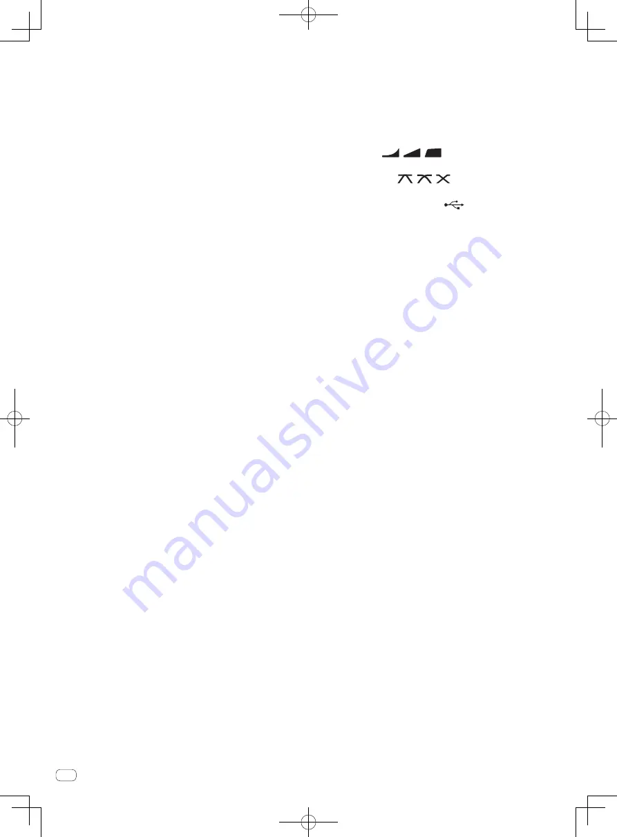
CH FADER (
,
,
) selector switch
Switches the channel fader’s curve characteristics.
y
CROSS FADER (
,
,
) curve selector switch
This switches the crossfader curve characteristics.
z
SEND/RETURN (1/4” JACK,
) selector switch
Switches the input/output source of the SEND/RETURN channel.
Select either the device connected to the [
SEND/RETURN
] terminal
on the control panel or the device connected to the mobile device
connection terminal.
A
RETURN TYPE (AUX, INSERT) selector switch
Selects the SEND/RETURN method.
B
Mobile device connection terminal (USB port)
Connect a mobile device to enable SEND/RETURN to be used for
apps.
C
SEND/RETURN ON/OFF button
Turns SEND/RETURN on and off.
D
SEND/RETURN LEVEL control
Adjusts the sound level of SEND/RETURN.
E
Main unit display
Displays the effect name, BPM, effect parameter, etc.
F
X-PAD
BEAT FX is on while this is touched. Also, the parameter can be
adjusted depending on the place touched.
G
BEAT
c
,
d
buttons
Set the beat fraction for synchronizing the effect sound.
H
TAP button
When the BPM measurement mode is set to [
TAP
], tap the button
with a finger to input the BPM manually.
I
QUANTIZE (UTILITY, WAKE UP) button
—
QUANTIZE
: When the QUANTIZE function is turned on for BEAT
FX, the effect is applied to the sound without getting out of tempo
with the currently playing track.
—
UTILITY
: Displays the [
UTILITY
] screen.
—
WAKE UP
: Cancels the standby state.
J
AUTO/TAP button
Switches the BPM measurement mode.
K
FX FREQUENCY button
Select the range to apply BEAT FX. BEAT FX is applied to the range of
the button that is lit.
L
Beat effect selector switch
Switches the BEAT FX effect type.
M
Effect channel selector switch
Switches the channel to which the BEAT FX is to be applied.
N
TIME control
Adjusts the BEAT FX’s time parameter.
O
LEVEL/DEPTH control
Adjusts the BEAT FX’s quantitative parameter.
P
Beat effect ON/OFF button
Turns BEAT FX on and off.
Содержание DJM-TOUR1
Страница 17: ...17 En Additional information...
Страница 18: ...18 En...


