Pima OutView Скачать руководство пользователя страница 4

OutView Installation Guide 


4  

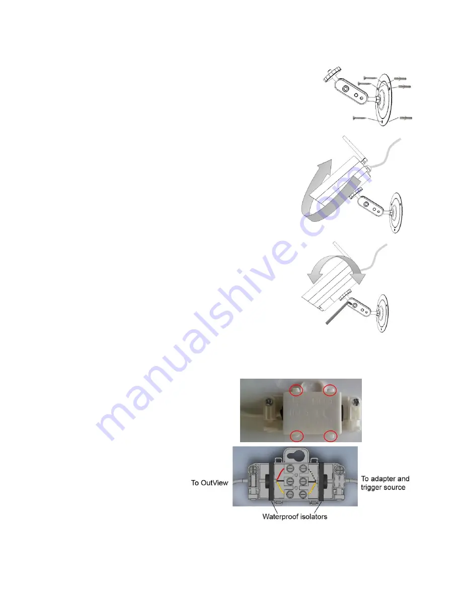
Follow the next steps to mount the camera: 
1.


Use the template on page 11 and drill 3 matching holes 
on the mounting surface. 

2.


Insert the supplied wall plugs and mount the bracket, 
using the supplied screws. 


3.


Rotate the swiveling bracket’s plastic knob clockwise, to its 

lower position. 

4.


Connect the camera to the bracket, by rotating it 

clockwise. 

5.


Tighten the plastic knob to secure the camera. 


6.


Connect the camera’s cable to the terminal block and to 
power; see the next section for details. 

7.


Adjust the field of view of the camera. 

8.


Tighten the bracket’s tilt screws with the supplied Allen 

wrench. 


How to connect the OutView 

The OutView is supplied connected with a 3-wire cable to a junction box. The box has a terminal 

block inside it. To connect the OutView, do the following: 
1.


Open the junction box: 

push the clasps (encircled 
in red in the image on the 

right) outside and remove  
the lid. 


2.


Pull out the black 
waterproof isolator, on the 

side without the wires. 


3.


Puncture a hole in the center of the isolator, for the wires of the AC adapter and the 

trigger source. 

4.


Put the required wires through the isolator. 

Содержание OutView

Страница 1: ...OutView Outdoor Wireless Camera Installation Guide...

Страница 2: ...Still Image Camera Operated by Momentary Trigger from N C Normally Close Devices Detectors Relays etc Up to 7 m Flash for Low Light Conditions Weather Resistant Sun Light Protection External AC adapt...

Страница 3: ...lash The AC adapter should be connected to an indoor AC outlet The distance between the camera and the trigger source detector cannot exceed 50 m Ensure that outdoor power cables such as extension cor...

Страница 4: ...lock and to power see the next section for details 7 Adjust the field of view of the camera 8 Tighten the bracket s tilt screws with the supplied Allen wrench How to connect the OutView The OutView is...

Страница 5: ...ic clip 8 Put the isolator now with the wires inserted into it back in its place 9 Replace the clip on the wires and fasten the screw 10 Close the lid and make sure it is fastened by all four clasps 1...

Страница 6: ...Up to 7 m RF Frequency 2 4 GHz ISM band Modulation Frequency Hopping Spread Spectrum FHSS Supervision 2 way Radio Link 20 sec interval Event Transmission Alarm Image Low Battery Supervision Range Up t...

Страница 7: ...y damage or loss whatsoever whether directly indirectly incidentally consequentially or otherwise caused by the malfunction of the Product due to products accessories or attachments of others includin...

Страница 8: ...to radio and television reception It has been type tested and found to comply with the limits for a Class B computing device in accordance with the specifications in Part 15 of FCC Rules which are des...

Страница 9: ...uide and the information contained herein are proprietary to PIMA Electronic Systems Ltd Only PIMA Electronic Systems Ltd or its customers have the right to use the information No part of this guide m...

Страница 10: ...10...

Страница 11: ...11...

Страница 12: ...Ltd 5 Hatzoref Street Holon 5885633 ISRAEL Tel 972 3 650 6414 Fax 972 3 550 0442 E mail support pima alarms com sales pima alarms com www pima alarms com Distributed and Supported by P N 4410383 4410...

Отзывы: