Pilz GmbH & Co. KG, Felix-Wankel-Straße 2, 73760 Ostfildern, Germany
Telephone: +49 711 3409-0, Telefax: +49 711 3409-133, E-Mail: [email protected]
6-1
6.1
General wiring guidelines
6
Wiring
6
6000
Wiring
Wiring
6-
6.1
General wiring guidelines
6100
General wiring guidelines
6-
][Verdrahtung BA Einleitung
Please note:
][Verdrahtung FS-Eingang
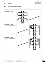
Appropriate wiring must be used to exclude short circuits between
the test pulse outputs and the corresponding input!
Appropriate wiring must be used to exclude short circuits between
the inputs or to a supply line!
The cable runs for the test pulses may be max. 200 m.
Signal lines do not have to be shielded.
Use copper wiring.
6.1.1
Mechanical connection of the base modules
Mechanical connection of the base modules
6-
][Modulverdrahtung mech
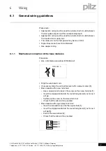
Procedure:
Use a flat blade screwdriver (DIN 5264-A)!
Strip the wire back 8 mm.
If necessary, label the connection level with a colour marker [3].
Base module with screw terminals:
– Use a screwdriver to loosen the screw on the screw terminal [1]
– Insert the stripped cable into the round fixing hole [2], as far as it
will go.
– Tighten up the screw on the screw terminal.
– Check that the cable is firmly seated.
Base module with cage clamp terminals:
– Insert the screwdriver [4] into the square hole [1].
– Insert the stripped cable into the round fixing hole [2], as far as it
will go [5].
– Pull out the screwdriver [6].
– Check that the cable is firmly seated.
DIN 5264-A
21
11
[1]
[3]
[2]


