background image

PNOZ s8

Operating Manual PNOZ s8
21400-EN-10

10

Wiring

Please note:

}

Information given in the "

Technical details [

 13]

" must be followed.

}

Outputs 13-14 and 23-24 are safety contacts, the semiconductor output Y32 is an auxil-
iary output (e.g. for display).

}

Semiconductor output Y32 should 

not

 be used for safety circuits!

}

To prevent contact welding, a fuse should be connected before the output contacts (see

Technical details [

 13]

).

}

Calculation of the max. cable length l

max 

in the input circuit:

R

lmax

R

/ km

I

max

 =

R

lmax

 = max. overall cable resistance (see 

Technical details [

 13]

)

R

l

 / km = cable resistance/km

}

Use copper wire that can withstand 60/75 °C.

}

Sufficient fuse protection must be provided on all output contacts with capacitive and in-
ductive loads.

}

Ensure the wiring and EMC requirements of EN 60204-1 are met.

}

The power supply must comply with the regulations for extra low voltages with protect-
ive electrical separation (SELV, PELV) in accordance with VDE 0100, Part 410.

Preparing for operation

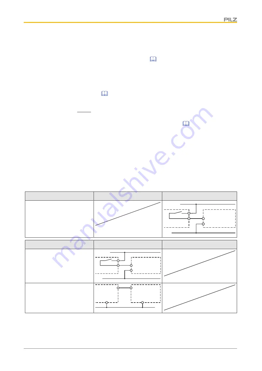
Supply voltage

AC

DC

A1

A2

24 V DC

0 V

PNOZsigma
expansion
module

Input circuit

Single-channel

Dual-channel

Base unit:
Safety relay PNOZ X

A1

A2

24 V DC

0 V

PNOZsigma
expansion
module

Base unit:
Safety relay PNOZelog
Driven via semiconductor outputs
(24 VDC)

A1

A2

0 V

O1

L-

PNOZsigma
expansion
module

Содержание PNOZ s8

Страница 1: ...PNOZ s8 Operating Manual 21400 EN 10 Safety relays...

Страница 2: ...nta tion will be gratefully received Source code from third party manufacturers or open source software has been used for some components The relevant licence information is available on the Internet...

Страница 3: ...ranty and liability 7 Disposal 7 For your safety 7 Unit features 8 Safety features 8 Block diagram terminal configuration 8 Function description 9 Timing diagram 9 Installation 9 Wiring 10 Preparing f...

Страница 4: ...Contents Operating Manual PNOZ s8 21400 EN 10 4 Remove plug in terminals 19 Order reference 19 EC declaration of conformity 19...

Страница 5: ...y important is identified as follows DANGER This warning must be heeded It warns of a hazardous situation that poses an immediate threat of serious injury and death and indicates preventive measures t...

Страница 6: ...the areas described in this manual Use of the product outside the technical details see Technical details 13 NOTICE EMC compliant electrical installation The product is designed for use in an industri...

Страница 7: ...e generic and specialist standards applicable to the spe cific application Warranty and liability All claims to warranty and liability will be rendered invalid if The product was used contrary to the...

Страница 8: ...ts the following safety requirements The unit monitors its own output contacts The safety function remains effective in the case of a component failure Earth fault in the feedback loop Detected depend...

Страница 9: ...terminator is inserted at the side of the unit Connect base unit and PNOZsigma contact expansion module Remove the plug terminator at the side of the base unit and at the contact expander module Conn...

Страница 10: ...chnical details 13 Rl km cable resistance km Use copper wire that can withstand 60 75 C Sufficient fuse protection must be provided on all output contacts with capacitive and in ductive loads Ensure t...

Страница 11: ...the mechanical contact on the relay cannot be tested automatically Depending on the operational environment measures to detect the non opening of switching elements may be required under some circums...

Страница 12: ...indicators FAULT Diagnostics Internal error unit defective Remedy Switch supply voltage off and then on again change unit if neces sary Faults malfunctions Contact malfunctions If the contacts have w...

Страница 13: ...750108 751108 Number 1 1 Voltage at Input circuit DC 24 V 24 V Current at Input circuit DC 65 mA 65 mA Max inrush current impulse Current pulse input circuit 0 6 A 0 6 A Pulse duration input circuit...

Страница 14: ...h UL Voltage 240 V AC G P 240 V AC G P With current 3 A 3 A Voltage 24 V DC G P 24 V DC G P With current 3 A 3 A Pilot Duty B300 R300 B300 R300 External contact fuse protection safety contacts In acco...

Страница 15: ...947 1 EN 60947 1 Overvoltage category III II III II Pollution degree 2 2 Rated insulation voltage 250 V 250 V Rated impulse withstand voltage 4 kV 4 kV Protection type Housing IP40 IP40 Terminals IP20...

Страница 16: ...comply with the safety related characteristic data in order to achieve the required safety level for your plant machine Operating Mode EN ISO 13849 1 2015 PL EN ISO 13849 1 2015 Category EN 62061 SIL...

Страница 17: ...in the service life table are not accessible the stated PFH value can be used irrespective of the switching frequency and the load as the PFH value already considers the relay s B10d value as well as...

Страница 18: ...e category Max rated impulse withstand voltage 3000 m 150 V II 2 5 kV 100 V III 2 5 kV 4000 m 150 V II 2 5 kV 100 V III 2 5 kV 5000 m 100 V II 1 5 kV 24 V III 0 8 kV Reduction of rated insulation volt...

Страница 19: ...nection type Order No PNOZ s8 24 VDC Screw terminals 750 108 PNOZ s8 C 24 VDC Spring loaded terminals 751 108 EC declaration of conformity This product these products meet the requirements of the dire...

Страница 20: ...yNET p THE SPIRIT OF SAFETY are registered and protected trademarks of Pilz GmbH Co KG in some countries We would point out that product features may vary from the details stated in this document depe...

Отзывы: