- 3 -
• Auf der Geräterückseite des PNOZ po3.3p
befinden sich 2 Buchsen. Das
Erweiterungsmodul PNOZ po3.3p wird mit
den anderen Geräten des modularen
Sicherheitssystems PNOZpower über die
mitgelieferten Steckbrücken verbunden.
Beachten Sie: Auf das erste und letzte
Gerät muss ein Abschlussstecker
gesteckt werden (siehe Fig. 2)!
• Nur Abschlussstecker für das modulare
Sicherheitssystem PNOZpower verwenden
(Aufdruck: Sach-Nr. 95579).
• Maximalbestückung eines PNOZpower-
Systems:
- 1 Basisgerät
- 4 Erweiterungsmodule
- 1 Netzgerät
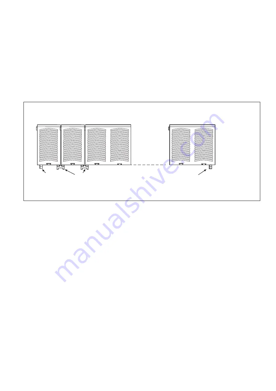
Fig. 2: Montage des PNOZ po3.3p/Installation PNOZ po3.3p/Montage du PNOZ po3.3p
Basisgerät
Base Unit
Appareil
de base
Erweiterungsmodul 1
Expander modul 1
Module d'expansion 1
PNOZ po3.3p
Erweiterungsmodul 4
Expander modul 4
Module d'expansion 4
Netzgerät
Power Supply
Bloc
d'alimentation
95579
Abschlussstecker
Terminator
Fiche de
terminaison
95425
Steckbrücke
Link
Cavalier de pontage
95579
Abschlussstecker
Terminator
Fiche de
terminaison
expander module to other units in the
PNOZpower modular safety system with
the jumpers supplied.
Please note: Be sure to plug a
terminator in to the first and last units
(see Fig. 2)!
• Only use terminators for the PNOZpower
modular safety system (Catalogue item no.
95579).
• Maximum hardware in a PNOZpower
system:
- 1 base unit
- 4 expander modules
- 1 power supply unit
• La face arrière du PNOZ po3.3p comporte
2 douilles. Le module d’extension PNOZ
po3.2p est relié aux autres appareils du
système de sécurité modulaire
PNOZpower par le biais des cavaliers de
pontage fournis.
Important : le premier et le dernier
appareil doivent être pourvus d’une
fiche de terminaison (voir fig. 2) !
• Utilisez uniquement les fiches de terminai-
son prévues pour le système de sécurité
modulaire PNOZpower (Référence :
95579).
• Équipement maximal d’un système
PNOZpower :
- 1 appareil de base
- 4 modules d’extension
- 1 bloc d’alimentation
Inbetriebnahme
Beachten Sie bei der Inbetriebnahme:
• ACHTUNG
Die steckbaren Anschlussklemmen nur im
spannungslosen Zustand ziehen und
stecken.
• Vor die Ausgangskontakte eine
Sicherung (s. technische Daten)
schalten, um das Verschweißen der
Kontakte zu verhindern.
• Keine kleinen Ströme mit Kontakten
schalten, über die zuvor große Ströme
geführt wurden.
• Leitungsmaterial aus Kupferdraht mit einer
Temperaturbeständigkeit von 60/75 °C
verwenden.
• Das Anzugsdrehmoment der Schrauben
auf den Anschlussklemmen muss 0,5 Nm
betragen.
• Angaben im Kapitel „Technische Daten“
unbedingt einhalten.
Ablauf
• Externer Start-/Stopp-Eingang Y39-Y40:
Brücken oder Taster (Öffnerkontakt)
anschließen
Das Gerät ist eingeschaltet, wenn
• die Versorgungsspannung anliegt (LED
"POWER" leuchtet)
• die Eingangskreise geschlossen sind
Die Sicherheitskontakte 1(L1)-2(T1), 3(L2)-
4(T2) und 5(L3)-6(T3) sind geschlossen und
die LEDs "CH. 1" und "CH. 2" leuchten. Wird
ein Eingangskreis geöffnet, öffnen die
Sicherheitskontakte 1(L1)-2(T1), 3(L2)-4(T2)
und 5(L3)-6(T3). Die LEDs "CH. 1" und "CH.
2" erlöschen.
Commissioning
When commissioning, please note the
following:
• CAUTION
Only connect and disconnect the plug-in
terminals when isolated from the mains.
• To prevent contact welding, a fuse
should be connected before the output
contacts (see technical details).
• Don’t switch low currents using contacts
that have been used previously with high
currents.
• Use copper wire that can withstand
60/75 °C.
• The torque setting on the connection
terminals should be 0.5 Nm.
• Information given in the “Technical details”
must be followed.
Sequence
• External start/stop input Y39-Y40:
connect links or button (N/C contact)
The unit is ready for operation when:
• the power supply via the PNOZpower bus is
present (“POWER” LED illuminates)
• the input circuits on the base unit are
made
The safety contacts 1(L1)-2(T1), 3(L2)-4(T2)
and 5(L3)-6(T3) are closed, and the LEDs
“CH. 1” and “CH. 2” illuminate. If an input
circuit on the base unit is open, then the
safety contacts 1(L1)-2(T1), 3(L2)-4(T2) and
5(L3)-6(T3) open also. The LEDs “CH. 1”
and “CH. 2” go out.
Mise en service
Points importants pour la mise en service :
• ATTENTION
Ne branchez et débranchez les borniers
de raccordement débrochables que
lorsque l’alimentation est coupée.
• Raccordez un fusible (voir les caracté-
ristiques techniques) avant les contacts
de sortie afin d’éliminer tout risque de
fusion.
• Ne commutez pas de courants de faible
intensité avec des contacts ayant servi à
des courants de forte intensité.
• Utilisez uniquement des fils de câblage en
cuivre résistant à des températures de 60/
75 °C.
• Le couple de serrage des vis doit être de
0,5 Nm au niveau des borniers.
• Respectez impérativement les instructions
données dans le chapitre “Caractéristiques
techniques”.
Procédure
• Circuit start/Stop externe Y39-Y40 : ponter
les 2 bornes ou relie un bouton poussoir
(contact à fermeture)
L’appareil est enclenché lorsque
• la tension d’alimentation est appliquée via le
bus PNOZpower (LED “POWER” allumée)
• les circuits d’entrée de l’appareil de base
sont fermés
Les contacts de sécurité 1(L1)-2(T1), 3(L2)-
4(T2) et 5(L3)-6(T3) sont fermés et les LEDs
“CH. 1” et “CH. 2” sont allumées. Si un circuit
d’entrée de l’appareil de base est ouvert, les
contacts de sécurité 1(L1)-2(T1), 3(L2)-4(T2)
et 5(L3)-6(T3) s’ouvrent et les LEDs “CH. 1”
et “CH. 2” s’éteignent.


