Function description
Operating Manual PNOZ m ES Profibus
1002698-EN-05
11
4
Function description
4.1
Operation
The virtual inputs and outputs that are to be transferred via PROFIBUS are selected and
configured in the PNOZmulti Configurator. The base unit and the expansion modulePNOZ
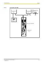
m ES Profibus are connected via a jumper.
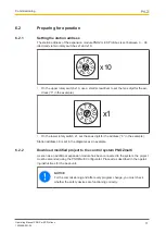
The station address is set via rotary switches. After the supply voltage is switched on or the
control system PNOZmulti 2 is reset, the expansion module PNOZ m ES Profibus is con-
figured and started automatically.
LEDs indicate the status of the expansion module on PROFIBUS.
The configuration is described in detail in the PNOZmulti Configurator's online help.
INFORMATION
The GSD file is available on the Internet at www.pilz.de.
4.2
Data access
The data is structured as follows:
}
Virtual data
–
Input area PNOZ m ES Profibus
The values for the inputs are set in the Master as an output and transferred to the
PNOZmulti 2.
–
Output area PNOZ m ES Profibus
The outputs are configured in the PNOZmulti Configurator and transferred to the
Master.
}
Status of LEDs:
Bits 0 … 4: Status of LEDs on the PNOZmulti 2
–
Bit 0: OFAULT
–
Bit 1: IFAULT
–
Bit 2: FAULT
–
Bit 3: DIAG
–
Bit 4: RUN
}
Data exchange is displayed in Bit 5.
}
Polling the payload data: 2 Bytes with the table number and segment number are sent
by the Master for access to the payload data table (15 Bytes are returned to the Mas-
ter).
Detailed information on data exchange (tables, segments) is available in the document
"Communication Interfaces" in the section entitled "Fieldbus modules".


