background image

PNOZ m ES Profibus

Operating Manual PNOZ m ES Profibus
1002698­EN­04

12

}

Install the expansion module in the position in which it is configured in the PNOZmulti
Configurator.

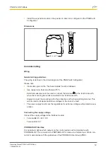
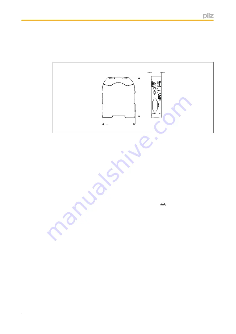
Dimensions

101,4 (4,11

)

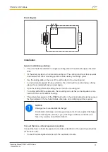
1

1

5

,0

 (4

,5

3

)

 22,5
(0,88“)

Commissioning

Wiring

General wiring guidelines

The wiring is defined in the circuit diagram of the PNOZmulti Configurator.

Please note:

}

Information given in the "Technical details" must be followed.

}

Use copper wire that can withstand 75°C.

}

External measures must be used to connect the terminal 

 to the functional earth,

when the mounting rail is 

not

 connected to the functional earth.

}

Always connect the mounting rail to the protective earth via an earthing terminal. This
will be used to dissipate hazardous voltages in the case of a fault.

}

The power supply must meet the regulations for extra low voltages with protective sep­
aration.

Connecting the supply voltage

Connect the supply voltage to the fieldbus module:

}

Terminal 

24 V

: + 24 V DC

}

Terminal 

0 V

: 0 V

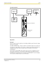
PROFIBUS DP interface

It is possible to define which outputs on the control system will communicate with
PROFIBUS­DP. The connection to PROFIBUS­DP is made via a female 9­pin D­Sub con­
nector in accordance with the guidelines of the PROFIBUS User Group (PNO).

Содержание PNOZ m ES Profibus

Страница 1: ...PNOZ m ES Profibus Operating Manual 1002698 EN 04 Configurable Control System PNOZmulti...

Страница 2: ...KG Copies may be made for internal purposes Suggestions and comments for improving this documentation will be gratefully received Pilz PIT PMI PNOZ Primo PSEN PSS PVIS SafetyBUS p SafetyEYE SafetyNET...

Страница 3: ...9 Operation 9 Data access 9 Assigning the inputs outputs in the PNOZmulti Configurator to the PROFIBUS DP in puts outputs 10 Block diagram 11 Installation 11 General installation guidelines 11 Connec...

Страница 4: ...Content Operating Manual PNOZ m ES Profibus 1002698 EN 04 4 Accessories 19...

Страница 5: ...as follows DANGER This warning must be heeded It warns of a hazardous situation that poses an immediate threat of serious injury and death and indicates preventive measures that can be taken WARNING T...

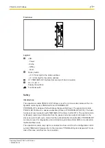
Страница 6: ...onfigurator Connection for PROFIBUS DP Station addresses from 0 99 selected via rotary switch Status indicators for communication with PROFIBUS DP and for errors In the PNOZmulti Configurator 128 virt...

Страница 7: ...hange at field level The expansion module PNOZ m ES Profibus is a passive subscriber Slave of PROFIBUS DP DPV0 The basic functions of communication with PROFIBUS DP conform to EN 50170 The central con...

Страница 8: ...used for this product Safety regulations Use of qualified personnel The products may only be assembled installed programmed commissioned operated maintained and decommissioned by competent persons A c...

Страница 9: ...Do not open the housing or make any unauthorised modifications Please make sure you shut down the supply voltage when performing maintenance work e g exchanging contactors Function description Operati...

Страница 10: ...ing the inputs outputs in the PNOZmulti Configurator to the PROFIBUS DP inputs outputs Virtual inputs and outputs can be requested or set directly via the following objects Each element can be selecte...

Страница 11: ...or end angle Open the locking slide before lifting the unit from the mounting rail To comply with EMC requirements the mounting rail must have a low impedance con nection to the control cabinet housi...

Страница 12: ...the functional earth when the mounting rail is not connected to the functional earth Always connect the mounting rail to the protective earth via an earthing terminal This will be used to dissipate ha...

Страница 13: ...1 5 9 6 1 n c 2 n c 3 B RxD TxD P 4 CNTR P 5 DGND 6 VP 7 n c 8 A RxD TxD N 9 n c n c not connected Please note the following when connecting to PROFIBUS DP Only use metal plugs or metallised plastic p...

Страница 14: ...in the example 1 2 3 4 9 8 7 6 0 5 x1 On the lower rotary switch x1 set the ones digit for the address 6 in the example Station address 36 is set in the diagrams as an example Download modified proje...

Страница 15: ...d The LEDs POWER DIAG FAULT IFAULT and OFAULT light up on the base unit The expansion module PNOZ m ES Profibus is configured and started automatically The ONLINE and OFFLINE LEDs indicate the status...

Страница 16: ...nge is not possible PNOZ m ES Profibus Not offline FAULT Application Watchdog Timeout 1 Hz Configuration error length of input and or output data during initialisation of the PNOZ m ES Profibus does n...

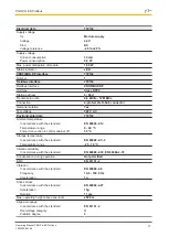
Страница 17: ...oltage 500 V AC Environmental data 772132 Ambient temperature In accordance with the standard EN 60068 2 14 Temperature range 0 60 C Forced convection in control cabinet off 55 C Storage temperature I...

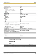
Страница 18: ...he same cross section flexible without crimp connectors or with TWIN crimp connectors 0 20 1 50 mm 24 16 AWG Rigid single core flexible multi core or multi core with crimp connector 0 5 1 5 mm Torque...

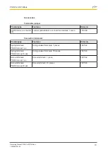
Страница 19: ...ck to connect the modules 1 piece 779 260 Connection terminals Product type Features Order no Spring terminals PNOZ mmcxp 1 pc Spring loaded terminals 1 pieces 783 542 Spring terminals PNOZ mmcxp 10 p...

Страница 20: ...mo PMCprotego PMCtendo PMD PMI PNOZ Primo PSEN PSS PVIS SafetyBUS p SafetyEYE SafetyNET p the spirit of safety are registered and protected trademarks of Pilz GmbH Co KG in some countries We would poi...

Отзывы: