background image

Technical details

Operating Manual PNOZ m B0
1002660-EN-07

33

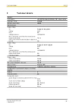
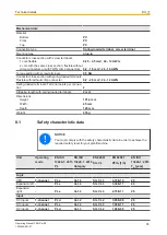
Configurable inputs/outputs (inputs or auxiliary
outputs)

Configurable auxiliary outputs

Voltage

24 V

Output current

75 mA

Output current range

0 - 100 mA

Max. transient pulsed current

500 mA

Short circuit-proof

yes

Residual current at "0"

0,5 mA

Voltage at "1"

UB - 2 V at 0.1 A

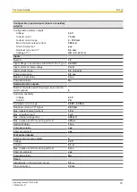
Inputs

Number

12

Input voltage in accordance with EN 61131-2 Type 1

24 V DC

Input current at rated voltage

5 mA

Input current range

2,5 - 5,3 mA

Pulse suppression

0,5 ms

Maximum input delay

2 ms

Potential isolation

No

Semiconductor outputs

Number of positive-switching single-pole semicon-
ductor outputs

4

Switching capability

Voltage

24 V

Current

2 A

Permitted current range

0,000 - 2,500 A

Residual current at "0" signal

0,05 mA

Max. transient pulsed current

12 A

Max. capacitive load

1 µF

Max. internal voltage drop

500 mV

Max. duration of off time during self test

330 µs

Switch-off delay

1 ms

Potential isolation

yes

Short circuit-proof

yes

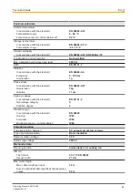
Test pulse outputs

Number of test pulse outputs

4

Voltage

24 V

Current

0,1 A

Max. duration of off time during self test

5 ms

Short circuit-proof

yes

Potential isolation

No

Times

Simultaneity in the two-hand circuit

0,5 s

Processing time

30 ms

Содержание PNOZ m B0

Страница 1: ...PNOZ m B0 Operating Manual 1002660 EN 07 Configurable safe small controllers PNOZmulti 2...

Страница 2: ...nta tion will be gratefully received Source code from third party manufacturers or open source software has been used for some components The relevant licence information is available on the Internet...

Страница 3: ...safety 11 Section 4 Function description 13 4 1 Integrated protection mechanisms 13 4 2 Functions 13 4 3 System reaction time 13 4 4 Block diagram 13 4 5 Diagnostics 14 Section 5 Installation 15 5 1 C...

Страница 4: ...30 7 2 4 Error stack on the LC display 31 Section 8 Technical details 32 8 1 Safety characteristic data 35 8 2 Classification according to ZVEI CB24I 36 Section 9 Supplementary data 38 9 1 Maximum cap...

Страница 5: ...particularly important is identified as follows DANGER This warning must be heeded It warns of a hazardous situation that poses an immediate threat of serious injury and death and indicates preventiv...

Страница 6: ...Introduction Operating Manual PNOZ m B0 1002660 EN 07 6 INFORMATION This gives advice on applications and provides information on special fea tures...

Страница 7: ...Semiconductor outputs 4 safety outputs Depending on the application up to PL e of EN ISO 13849 1 and up to SIL CL 3 of EN IEC 62061 12 inputs for connecting for example Emergency stop pushbutton Two...

Страница 8: ...orts between the safety outputs Plug in connection terminals Either spring loaded terminal or screw terminal available see Order references Rotary knob for menu control Expansion modules can be connec...

Страница 9: ...ith and without cover Legend X1 Inputs I8 I15 X2 Configurable test pulse auxiliary outputs T0M20 T3M23 Semiconductor outputs O0 O3 X3 Configurable inputs outputs IM0 IM3 Inputs I4 I7 X4 Configurable i...

Страница 10: ...h protection type IP54 and cor responding air conditioning The following is deemed improper use in particular Any component technical or electrical modification to the product Use of the product outsi...

Страница 11: ...provided in the section entitled Safety Have a good knowledge of the generic and specialist standards applicable to the spe cific application 3 3 3 Warranty and liability All claims to warranty and l...

Страница 12: ...07 12 Adequate protection must be provided for all inductive consumers Do not open the housing or make any unauthorised modifications Please make sure you shut down the supply voltage when performing...

Страница 13: ...h other They evaluate the input circuits on the base unit and expansion modules and switch the outputs on the base unit and expansion modules accordingly The LEDs on the base unit and expansion module...

Страница 14: ...al PNOZ m B0 1002660 EN 07 14 4 5 Diagnostics The status and error messages displayed by the LEDs are saved in an error stack This er ror stack can be shown on the display or can be read from the PNOZ...

Страница 15: ...efore lifting the unit from the mounting rail To comply with EMC requirements the mounting rail must have a low impedance con nection to the control cabinet housing NOTICE Damage due to electrostatic...

Страница 16: ...distances Heat producing unit Heat producing unit INFORMATION Please note that at the stated minimum distance it will be difficult to swap the chip card from above If you cannot leave a greater dista...

Страница 17: ...ting Manual PNOZ m B0 1002660 EN 07 17 5 2 Dimensions in mm with spring loaded terminals 5 3 Install base unit without expansion module Make sure that the terminators are inserted on the top left and...

Страница 18: ...of modules that can be connected to the base unit and the module types The modules are linked via jumpers Remove the terminator on the side of the base unit and on the expansion module Install the bas...

Страница 19: ...aration Test pulse outputs must exclusively be used to test the inputs They must not be used to drive loads Do not route the test pulse lines together with actuator cables within an unprotected multic...

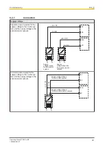
Страница 20: ...utputs 24 V DC 0 V DC Supply voltage infeed for the control system Supply voltage infeed for the semiconductor outputs 0 V DC 24 V DC N L1 N L1 A1 A2 24V 0V Common power supply for the supply voltage...

Страница 21: ...IM0 L S1 IM1 IM0 L L Emergency stop with detection of shorts across contacts IM0 T0M20 S1 S1 T1M21 IM1 T0M20 IM0 Start circuit Input circuit without detection of shorts across contacts Input circuit w...

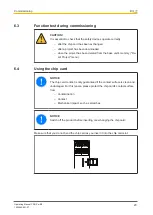
Страница 22: ...p card containing the current project into the card slot on the base unit Switch on the supply voltage The LC display shows the project name CRC sum and the date the project was created Please check t...

Страница 23: ...been deleted from the base unit s memory Re set Project menu 6 4 Using the chip card NOTICE The chip card contact is only guaranteed if the contact surface is clean and undamaged For this reason plea...

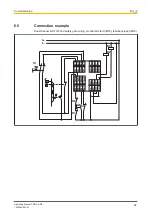
Страница 24: ...5 Connection example Dual channel E STOP and safety gate wiring monitored start IM18 feedback loop IM16 IM0 IM1 IM2 IM3 I4 I5 I6 I7 I8 I9 I10 I11 I12 I13 I14 I15 IM16 IM17 IM18 IM19 T0 M20 T1 M21 T2 M...

Страница 25: ...fe condi tion e g chip card not inserted External error on the base unit outputs e g short across the contacts leading to a safe condition Internal error on the base unit Internal error on the base un...

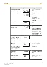
Страница 26: ...op Line 1 4 Status and error messages as short text DISPLAY MESSAGE Display messages E STOP pressed Line 1 4 Customised messages that are created in the PNOZmulti Configur ator PROJECT INFO Project in...

Страница 27: ...00 EC 83 00 00 EN 01 CH A 1st line Consecutive num ber 2nd line Error class EC and error information EI 3rd line Error number EN and error parameter PA 4th line Continuation of er ror parameter PA IP...

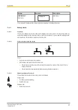
Страница 28: ...d or with a screwdriver If you make the settings with a screwdriver the knob can remain within the unit 7 2 1 2 Pull out and retract the knob 1 2 Knob A pull out until it locks into position B release...

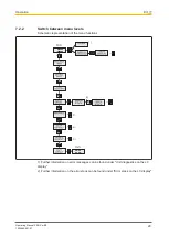
Страница 29: ...Switch between menu levels Schematic representation of the menu functions 2 1 Further information on error messages can be found under Unit diagnostics on the LC display 2 Further information on the e...

Страница 30: ...Chip card is not inserted blank or unread able FAULTY TEST PULSE Error caused by test pulses PARTIALLY OPERATED Function element was or is partially oper ated FEED BACK LOOP Exernal error at the feed...

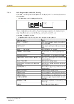
Страница 31: ...he LC display Sequential number of an error stack entry A new error stack entry is stored in first place Error class EC and error information EI Error number EN and five error parameters PA Procedure...

Страница 32: ...ly voltage for Supply to the SC outputs Voltage 24 V Kind DC Voltage tolerance 20 25 Max continuous current that the external power supply must provide 8 A Potential isolation yes Supply voltage Curre...

Страница 33: ...mum input delay 2 ms Potential isolation No Semiconductor outputs Number of positive switching single pole semicon ductor outputs 4 Switching capability Voltage 24 V Current 2 A Permitted current rang...

Страница 34: ...cy 5 150 Hz Acceleration 1g Shock stress In accordance with the standard EN 60068 2 27 Acceleration 15g Duration 11 ms Airgap creepage In accordance with the standard EN 61131 2 Overvoltage category I...

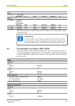
Страница 35: ...terminals Terminal points per connec tion 2 Stripping length with spring loaded terminals 9 mm Dimensions Height 101 4 mm Width 45 mm Depth 120 mm Weight 235 g 8 1 Safety characteristic data NOTICE Yo...

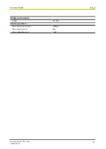
Страница 36: ...e used and may be different We recommend that you use the PAScal software tool to calculate the safety function s SIL PL values 8 2 Classification according to ZVEI CB24I The following tables describe...

Страница 37: ...Technical details Operating Manual PNOZ m B0 1002660 EN 07 37 Single pole output Class C1 C2 Source parameters Max test pulse duration 330 s Max rated current 2 A Max capacitive load 1 F...

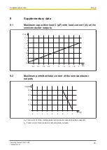
Страница 38: ...at the semiconductor outputs 4 8 12 16 20 0 0 2 0 4 0 6 0 8 1 1 2 1 4 1 6 1 8 2 I A C F 9 2 Maximum permitted total current of the semiconductor outputs 100 200 300 400 0 1 2 3 4 5 6 7 8 IHL A ICfg m...

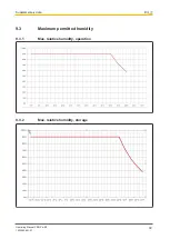
Страница 39: ...Supplementary data Operating Manual PNOZ m B0 1002660 EN 07 39 9 3 Maximum permitted humidity 9 3 1 Max relative humidity operation 9 3 2 Max relative humidity storage...

Страница 40: ...pe Features Order no PNOZ mm0 xp terminator left Terminator black yellow x1 779 261 Cable Product type Features Order no PSSu A USB CAB03 Mini USB cable 3 m 312 992 PSSu A USB CAB05 Mini USB cable 5 m...

Страница 41: ...NET p THE SPIRIT OF SAFETY are registered and protected trademarks of Pilz GmbH Co KG in some countries We would point out that product features may vary from the details stated in this document depen...

Отзывы: