background image

P2HZ X4P

Operating Manual P2HZ X4P
20076-EN-08

19

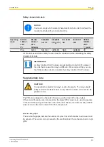
Safety characteristic data

NOTICE

You must comply with the safety characteristic data in order to achieve the
required safety level for your plant/machine.

Operating
mode

EN ISO
13849-1:
2015

PL

EN ISO
13849-1:
2015

Category

EN 62061

SIL CL

EN 62061

PFH

D

 [1/h]

IEC 61511

SIL

IEC 61511

PFD

EN ISO
13849-1:
2015

T

M

 [year]

PL e

Cat. 4

SIL CL 3

3,01E-09

SIL 3

3,24E-06

20

All the units used within a safety function must be considered when calculating the safety
characteristic data.

INFORMATION

A safety function's SIL/PL values are 

not

 identical to the SIL/PL values of

the units that are used and may be different. We recommend that you use
the PAScal software tool to calculate the safety function's SIL/PL values.

Supplementary data

CAUTION!

It is essential to consider the relay's service life graphs. The relay outputs'
safety-related characteristic data is only valid if the values in the service life
graphs are met.

The PFH value depends on the switch frequency and the load of the relay output.
If the service life graphs are not accessible, the stated PFH value can be used irrespective
of the switch frequency and the load, as the PFH value already considers the relay's B10d
value as well as the failure rates of the other components.

Service life graph

The service life graphs indicate the number of cycles from which failures due to wear must
be expected. The wear is mainly caused by the electrical load; the mechanical load is negli-
gible.

Содержание P2HZ X4P

Страница 1: ...P2HZ X4P Operating Manual 20076 EN 08 Safety relays ...

Страница 2: ...enta tion will be gratefully received Source code from third party manufacturers or open source software has been used for some components The relevant licence information is available on the Internet on the Pilz homepage Pilz PIT PMI PNOZ Primo PSEN PSS PVIS SafetyBUS p SafetyEYE SafetyNET p the spirit of safety are registered and protected trademarks of Pilz GmbH Co KG in some countries SD means...

Страница 3: ... 6 Disposal 6 For your safety 6 Unit features 7 Safety features 7 Block diagram terminal configuration 8 Types DC 8 Types AC 8 Function Description 9 Operating modes 9 Timing diagram 9 Installation 10 Wiring 11 Preparing for operation 12 Operation 12 Status indicators 13 Faults Interference 13 Dimensions in mm 13 Technical details 14 Safety characteristic data 19 Supplementary data 19 Service life...

Страница 4: ...rly important is identified as follows DANGER This warning must be heeded It warns of a hazardous situation that poses an immediate threat of serious injury and death and indicates preventive measures that can be taken WARNING This warning must be heeded It warns of a hazardous situation that could lead to serious injury and death and indicates preventive measures that can be taken CAUTION This re...

Страница 5: ...he supply voltage for the two hand control relay must only be connected downstream of the shutdown device in accordance with 9 VBG 7n5 1 2 The following is deemed improper use in particular Any component technical or electrical modification to the product Use of the product outside the areas described in this manual Use of the product outside the technical details see Technical details 19 NOTICE E...

Страница 6: ...iliar with the basic regulations concerning health and safety accident preven tion Have read and understood the information provided in the section entitled Safety Have a good knowledge of the generic and specialist standards applicable to the spe cific application Warranty and liability All claims to warranty and liability will be rendered invalid if The product was used contrary to the purpose f...

Страница 7: ...h status of the safety contacts Plug in connection terminals either spring loaded terminal or screw terminal Safety features The two hand control relay meets the following safety requirements The circuit is redundant with built in self monitoring The safety function remains effective in the case of a component failure The circuit prevents a further press stroke in the case of Relay failure Contact...

Страница 8: ...ion between the non marked area and the relay contacts Basic insulation over voltage category III Protective separation overvoltage category II Types AC UB 24 VAC Order no 777354 787354 Insulation between the non marked area and the relay contacts Basic insulation over voltage category III Protective separation overvoltage category II ...

Страница 9: ...operator element is released following simultaneous operation Safety contacts 13 14 23 24 and 33 34 are opened redundantly auxiliary contact 41 42 is closed The LED CH1 or CH2 goes out To activate the device again both operator elements have to be released and then op erated again within the simultaneity Operating modes Dual channel operation with detection of shorts across contacts Redundant inpu...

Страница 10: ...it by using a fixing element e g retaining bracket or end angle Fit the input terminal block of the control cabined with additional terminals for the supply voltage WARNING Loss of the safety function due to too short distance of the operator elements to the hazardous area The distance of the two hand control relay to the nearest hazardous area must be large enough so that if one of the operator e...

Страница 11: ... be switched off with the operating energy of the machine The connection cables between the P2HZ X4P and the pushbuttons should not be laid directly next to power cables otherwise inductive and capacitive interference coupling can result On account of the low currents you should use gold plated pushbutton contacts Only contactors with positive guided contacts should be used for safety functions Su...

Страница 12: ...ending on the operational environment measures to detect the non opening of switching elements may be required under some circumstances When the product is used in accordance with the European Machinery Directive a check must be carried out to ensure that the safety contacts on the relay outputs open correctly Open the safety contacts switch off output and start the device again so that the intern...

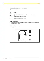
Страница 13: ... Supply voltage is present and E STOP pushbutton not operated CH 1 Safety contacts of channel 1 are closed CH 2 Safety contacts of channel 2 are closed Faults Interference Contact malfunctions If the contacts have welded reactivation will not be possible after the input circuit has opened Dimensions in mm with spring loaded terminals ...

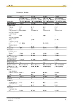
Страница 14: ... 50 60 Hz 50 60 Hz Residual ripple DC 10 10 Duty cycle 100 100 100 100 Current at Normally open contact 15 mA 15 mA 15 mA 15 mA N C 25 mA 20 mA 25 mA 20 mA Max overall cable resistance Rlmax per input circuit 14 Ohm 14 Ohm 14 Ohm 14 Ohm External unit fuse protection F1 min 1 A 1 A 1 A 1 A External unit fuse protection F1 max Max conductor cross section Max conductor cross section Max conductor cro...

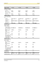
Страница 15: ...t 24 V 24 V 24 V 24 V Min current 0 01 A 0 01 A 0 01 A 0 01 A Max current 5 A 5 A 5 A 5 A Max power 125 W 125 W 125 W 125 W Utilisation category of auxiliary contacts AC1 at 240 V 240 V 240 V 240 V Min current 0 01 A 0 01 A 0 01 A 0 01 A Max current 2 5 A 2 5 A 2 5 A 2 5 A Max power 600 VA 600 VA 600 VA 600 VA DC1 at 24 V 24 V 24 V 24 V Min current 0 01 A 0 01 A 0 01 A 0 01 A Max current 2 5 A 2 5...

Страница 16: ...300 R300 External contact fuse protection safety contacts In accordance with the standard EN 60947 5 1 EN 60947 5 1 EN 60947 5 1 EN 60947 5 1 Max melting in tegral 100 A s 100 A s 100 A s 100 A s Blow out fuse quick 6 A 6 A 6 A 6 A Blow out fuse slow 4 A 4 A 4 A 4 A Blow out fuse gG 6 A 6 A 6 A 6 A Circuit breaker 24V AC DC char acteristic B C 4 A 4 A 4 A 4 A External contact fuse protection aux i...

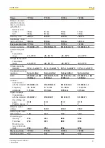
Страница 17: ...C 93 r h at 40 C Condensation during operation Not permitted Not permitted Not permitted Not permitted EMC EN 60947 5 1 EN 61000 6 2 EN 60947 5 1 EN 61000 6 2 EN 60947 5 1 EN 61000 6 2 EN 60947 5 1 EN 61000 6 2 Vibration In accordance with the standard EN 60068 2 6 EN 60068 2 6 EN 60068 2 6 EN 60068 2 6 Frequency 10 55 Hz 10 55 Hz 10 55 Hz 10 55 Hz Amplitude 0 35 mm 0 35 mm 0 35 mm 0 35 mm Airgap ...

Страница 18: ... mm 24 12 AWG 2 core with the same cross sec tion flexible with crimp connectors no plastic sleeve 0 25 1 mm 24 16 AWG 0 25 1 mm 24 16 AWG 2 core with the same cross sec tion flexible without crimp connectors or with TWIN crimp connectors 0 2 1 5 mm 24 16 AWG 0 2 1 5 mm 24 16 AWG Torque setting with screw terminals 0 5 Nm 0 5 Nm Conductor cross section with spring loaded terminals Flexible with wi...

Страница 19: ... be different We recommend that you use the PAScal software tool to calculate the safety function s SIL PL values Supplementary data CAUTION It is essential to consider the relay s service life graphs The relay outputs safety related characteristic data is only valid if the values in the service life graphs are met The PFH value depends on the switch frequency and the load of the relay output If t...

Страница 20: ...oted With DC con tactors use flywheel diodes for spark suppression Order reference Product type Features Connection type Order no P2HZ X4P C 24 V AC Spring loaded terminals 787 354 P2HZ X4P 24 V AC Screw terminals 777 354 P2HZ X4P C 24 VDC Spring loaded terminals 787 355 P2HZ X4P 24 VDC Screw terminals 777 355 EC declaration of conformity This product these products meet the requirements of the di...

Страница 21: ...tyNET p THE SPIRIT OF SAFETY are registered and protected trademarks of Pilz GmbH Co KG in some countries We would point out that product features may vary from the details stated in this document depending on the status at the time of publication and the scope of the equipment We accept no responsibility for the validity accuracy and entirety of the text and graphics presented in this information...

Отзывы: