background image

Commissioning

Operating Manual PNOZ ml1p
21575-EN-06

19

6.4

Connection examples

6.4.1

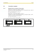
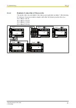
Example: Series connection of 3 base units

Reaction time t

SUM

 between base unit Base 1 and Base 2:

Input delay t

ON

 at I3 and I6 + data transmission time1 * t

BUS

 through link switch-off

delay t

COND

 of the semiconductor output at O0

t

SUM

 = t

ON

 + (n * t

BUS

) + t

COND

t

SUM

 = 4 ms + (1 * 35 ms ) + 30 ms = 69 ms

Reaction time t

SUM

 between base unit Base 1 and Base 3:

Input delay t

ON

 at I3 und I6 + data transmission time 2 * t

BUS

 through link m switch-

off delay t

COND

 of the semiconductor output at O1

t

SUM

 = t

ON

 + (n * t

BUS

 ) + t

COND

t

SUM

 = 4 ms + (2 * 35 ms ) + 30 ms = 104 ms

CHIP-Card

Shield

CHIP-Card

CHIP-Card

Shield

Shield

Shield

S1

K2

K3

I3 I6

O0

O1

Base 1

Base 2

Base 3

Содержание 773540

Страница 1: ...PNOZ ml1p Operating Manual 21575 EN 06 Configurable safety systems PNOZmulti...

Страница 2: ...umentation will be gratefully received Source code from third party manufacturers or open source software has been used for some components The relevant licence information is available on the Interne...

Страница 3: ...on 4 Function Description 12 4 1 Integrated protection mechanisms 12 4 2 Functions 12 4 3 System reaction time 14 4 4 Block diagram 14 Section 5 Installation 15 5 1 General installation guidelines 15...

Страница 4: ...Contents Operating Manual PNOZ ml1p 21575 EN 06 4 Section 9 Order reference 26 9 1 Product 26 9 2 Accessories 26...

Страница 5: ...particularly important is identified as follows DANGER This warning must be heeded It warns of a hazardous situation that poses an immediate threat of serious injury and death and indicates preventive...

Страница 6: ...Introduction Operating Manual PNOZ ml1p 21575 EN 06 6 INFORMATION This gives advice on applications and provides information on special fea tures...

Страница 7: ...lowing features Can be configured in the PNOZmulti Configurator Point to point connection via 4 core shielded and twisted pair cable 32 virtual inputs and 32 virtual outputs Status indicators Plug in...

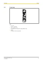
Страница 8: ...Overview Operating Manual PNOZ ml1p 21575 EN 06 8 2 3 Front view Shield Key 0 V 24 V Supply connections CA CA CB CB Connections for 2 expansion modules PNOZ ml1p Shield Connection for the cable shield...

Страница 9: ...increased environmental requirements see Technical details 22 The following is deemed improper use in particular Any component technical or electrical modification to the product Use of the product ou...

Страница 10: ...ipment devices systems plant and machinery in accordance with the general standards and guidelines for safety technology It is the company s responsibility only to employ personnel who Are familiar wi...

Страница 11: ...re met This operating manual only describes the basic functions of the unit The expanded functions are described in the PNOZmulti Configurator s online help Only use these functions once you have read...

Страница 12: ...switch the outputs on the base unit and expansion modules accordingly The LEDs on the base unit and expansion modules indicate the status of the configurable control system PNOZmulti The online help...

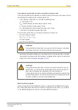
Страница 13: ...ule a calculation must always be made in accordance with the above formulas Input delay and switch off delay are only included once in the reaction time The data transmission time between the link mod...

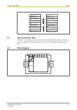
Страница 14: ...s i0 i31 Virtual outputs o0 o31 4 3 System reaction time Calculation of the maximum reaction time between an input switching off and a linked out put in the system switching off is described in the do...

Страница 15: ...rail in an upright position so that the earthing springs on the control system are pressed on to the mounting rail The ambient temperature of the PNOZmulti units in the control cabinet must not excee...

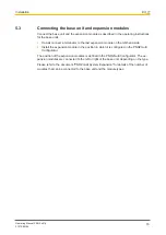
Страница 16: ...on module on the left hand side Install the expansion module in the position in which it is configured in the PNOZmulti Configurator The position of the expansion modules is defined in the PNOZmulti C...

Страница 17: ...cable length may be max 100 m The reduced cable length must be configured in the PNOZmulti Configurator Connect the inputs and outputs from two PNOZ ml1p with a 4 core shielded cable The cables must...

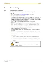
Страница 18: ...o the system the project must be amended using the PNOZmulti Configurator Proceed as described in the operat ing instructions for the base unit NOTICE For the commissioning and after every program cha...

Страница 19: ...ule switch off delay tCOND of the semiconductor output at O0 tSUM tON n tBUS tCOND tSUM 4 ms 1 35 ms 30 ms 69 ms Reaction time tSUM between base unit Base 1 and Base 3 Input delay tON at I3 und I6 dat...

Страница 20: ...xample 1 After pressing S1 on Base 1 the semiconductor outputs switch after the following reaction times tSUM O0 on Base 1 69 ms O1 on Base 3 104 ms O0 on Base 4 139 ms O0 on Base 5 104 ms CHIP Card S...

Страница 21: ...r operation The unit is not ready for operation FAULT Red External error Red Internal error No fault TR Yel low Connection to another PNOZ ml1p available No connection to another PNOZ ml1p 7 2 Fault d...

Страница 22: ...ly interruption before de ener gisation 20 ms 20 ms Max data transmission time 35 ms 35 ms Environmental data 773540 773545 Ambient temperature In accordance with the standard EN 60068 2 14 EN 60068 2...

Страница 23: ...22 35 x 7 5 EN 50022 Recess width 27 mm 27 mm Max cable length between two link modules 1 km 1 km Material Bottom PPO UL 94 V0 PPO UL 94 V0 Front ABS UL 94 V0 ABS UL 94 V0 Connection type Spring loade...

Страница 24: ...24 Mechanical data 773540 773545 Stripping length with spring loaded terminals 9 mm 9 mm Dimensions Height 94 0 mm 94 0 mm Width 22 5 mm 22 5 mm Depth 121 0 mm 121 0 mm Weight 129 g 135 g Where stand...

Страница 25: ...y EN 62061 SIL CL EN 62061 PFHD 1 h IEC 61511 SIL IEC 61511 PFD EN ISO 13849 1 2015 TM year 2 channel PL e Cat 4 SIL CL 3 8 82E 09 SIL 3 3 86E 05 20 All the units used within a safety function must be...

Страница 26: ...PNOZ mli1p 10m screw Cable 5 pin shielded screw terminal 10 m 773 891 PNOZ mli1p 50m screw Cable 5 pin shielded screw terminal 50 m 773 892 PNOZ mli1p 5m spring Cable 5 pin shielded spring loaded term...

Страница 27: ...T p ThE SPIrIT Of SAfETY are registered and protected trademarks of Pilz Gmbh Co KG in some countries We would point out that product features may vary from the details stated in this document dependi...

Отзывы: