


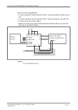


Connection to control systems and evaluation devices
Operating Manual PSEN ml sa 1.1/2.1/2.2, PSEN ml DHM
1005457-EN-02
| 33
6.4
Series connection
CAUTION!
Extension of delay-on de-energisation
When several (n) devices are connected in series, the delay-on de-ener-
gisation time adds with the number of interconnected safety switches.
The max. delay-on de-energisation is made up of the
risk time (see
+ (n-1) x max. delay-on de-energisation of the inputs
+ max. delay-on de-energisation of the evaluation device
Up to 16 safety switches can be configured in series.
In practice, the maximum possible number will be limited by the following parameters,
among others:
}
The required SIL level (e.g. SIL CL 3),
}
the required performance level (e.g. PL e (Cat. 4)),
}
the maximum delay or risk time permitted by the application,
}
Cable length (see notes on cable lengths),
}
Height of supply voltage.
Ensure there is sufficient supply voltage, taking inrush currents and fusing into considera-
tion.
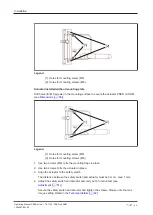
Notes on cable lengths
}
Determine the values under the following conditions:
Room temperature (25°C), conductor cross section 0.25 mm
2
, output load per output
(12, 22, Y32) each ≤ 10mA
[1]
L1
[2]
[2]
[2]
L2
L3
L4
L5
L6
[2]
[2]
[2]
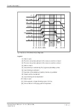
Legend
[1] Safety control system
[2] Safety switch PSEN ml