


Function description
Operating Manual PSEN ml s 1.1/2.1/2.2
1004710-EN-05
| 25
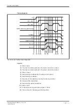
INFORMATION
If guard locking is deactivated using the auxiliary release, there is a low sig-
nal at safety outputs 12 and 22. An error code will be issued (see under
) and the safety switch switches to a fault condition.
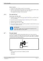
Mode of operation
In the danger zone, if the button of the escape release pin is pressed towards the safety
gate, the escape release impacts directly on the auxiliary release of the safety switch and
the auxiliary release unlocks the safety gate. The safety gate can be opened immediately,
enabling the operator to leave the danger zone.
There is a low signal at safety outputs 12 and 22 if the escape release was operated.
Scope
}
Scope of supply stationary escape release
– 1 escape release stationary
– 1 adapter disk
– 2 screws for adapter disk
– 4 screws for installation on the adapter disk
}
Scope of supply external escape release
– 1 escape release external with installed push/pull cables (see
)
– 1 adapter disk
– 2 screws for adapter disk
– 4 screws for installation on the adapter disk
4.8.1
Recommissioning
1. Reset the handle.
2. Switch the voltage off and then on again.
3. Carry out a function test using the escape release. The safety function may only be
checked by qualified personnel.