background image

3.4 Adding a Slide Switch 

1.   Now let’s attach a slide switch and use it to control the speed of flashes on the LED. 

2.  Attach the Slide Switch module to P0 on the edge of your Micobric motherboard next to the 

LED module (note the 0 and 1 written in gold on the module). 


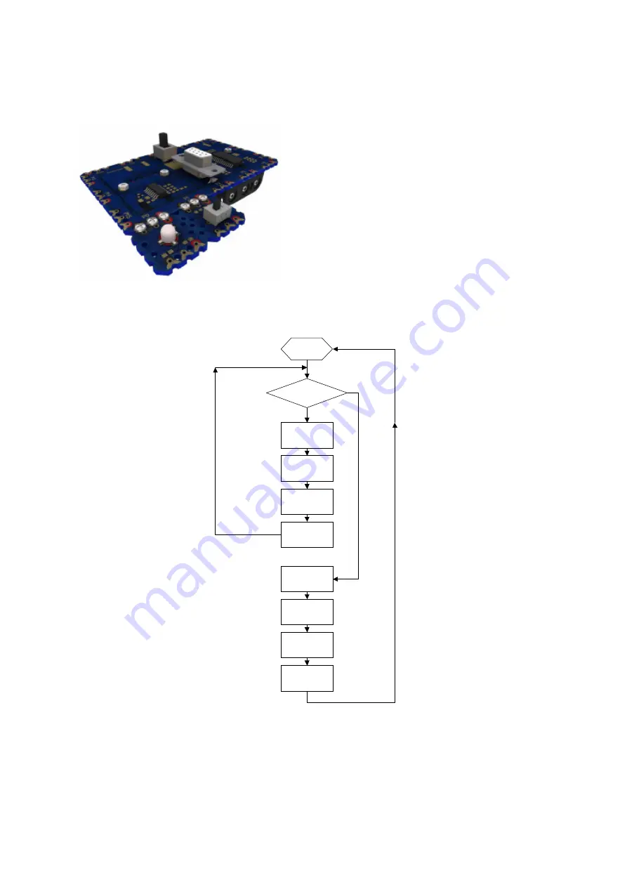
3.  Again, let’s draw a flow diagram before we write the program. Here is one for the program we 

will write. 

START 

Turn on LED 

Keep on for 

200 

milliseconds 

Turn off LED 

Keep off for 

200 

milliseconds 

Is switch 

on? 

Turn on LED 

Keep on for 

2000 

milliseconds 

Turn off LED 

Keep off for 

2000 

milliseconds 

Yes 

No 


Содержание Versabot

Страница 1: ...The Versabot Manual July 2009...

Страница 2: ...e 3 2 Pin Numbers 3 3 Making a LED flash 3 4 Adding a slide switch 3 5 Adding a buzzer 3 6 The push button 3 7 The motor forwards backward 3 8 Using bump sensors 3 9 The infrared receiver 4 Building y...

Страница 3: ...s New Possibilities for construction and New Code for programming as well as finding out the latest news in Versabot electronics If you follow the manual through from start to finish you will learn ev...

Страница 4: ...ed on Slide Switch module This module contains a small switch and the circuitry to drive it A switch allows us to turn an electronic device on or switch between two electronic functions Buzzer module...

Страница 5: ...em up firmly but not too tight 3 Make sure that the Bric is the right way around It will only fit one way you do not need to force pieces together 2 4 Connecting the Batteries The motherboard is power...

Страница 6: ...t up the other way it will sit straight i e 4 Fit the Bric into the holes at P0 on the motherboard 5 Now screw in three screws firmly to complete the connection If you ve done it correctly your Module...

Страница 7: ...to C 6 and so forth This situation is very common in computer engineering where a general purpose programmable chip is used with specific hardware and is very easy to deal with All that is required i...

Страница 8: ...o draw a flow chart of how the program will work Here is an example of a flow chart that shows what our program will do START Turn on LED Keep on for 200 milliseconds Turn off LED Keep off for 200 mil...

Страница 9: ...ant to have a copy of your program you must save it to disk 11 Make sure the download cable is securely connected to your computer and to the download connector on your Versabot motherboard Also make...

Страница 10: ...motherboard next to the LED module note the 0 and 1 written in gold on the module 3 Again let s draw a flow diagram before we write the program Here is one for the program we will write START Turn on...

Страница 11: ...This tells the microcontroller to expect input at this pin We also add the symbol definition for IN1 at the top of the program 5 Save your program as SlideSwitchprogram bas 6 Press the F5 key or use t...

Страница 12: ...pin note1 duration1 note2 duration2 noteX durationX pin this is the pin number that the buzzer is connected to i e P2 note is a number between 1 and 127 that specifies the frequency of the note durat...

Страница 13: ...ll keep looping and will test the condition each time before it proceeds As soon as that condition changes i e The switch is moved to the 0 position it will break out of the loop and continue through...

Страница 14: ...e 200 Keep P0 high for 200ms low P0 Set P0 low 0V pause 200 Keep P0 low for 200ms else Otherwise slide switch is a 0 sound P2 100 50 110 50 Play two high tones pause 500 And delay between tones end if...

Страница 15: ...LED on pause 1000 Leave on for 1000ms 1s return And return from subroutine Some things to note about the program above This time we have defined a variable called PushButton at the very beginning of t...

Страница 16: ...which ranges from 0 to 255 PULSOUT pin time pin this is the pin number the motor is connected to time the duration of the pulse measured in milliseconds 3 Start the Programming Editor or AXEpad or st...

Страница 17: ...pinB 5 Define Input P5 high P4 Set the motor line high pause 50 Wait for motor module to be ready do Do the following low P0 Initialise the LED off do Go forwards serout P4 T2400 C 150 Drive motor clo...

Страница 18: ...8 The motor should start turning the wheel clockwise When the bumper is pushed the LED should light and the wheel should change direction to anticlockwise...

Страница 19: ...nfigured to work with your microcontroller Note that buttons A C D E F and G are for setting the remote control into different modes which are not required for this project Avoid pressing these button...

Страница 20: ...backwards gosub WaitWhileKeyHeld Wait for key release pulsout P4 6 Stop Motor return LightLED high P0 Turn LED on pause 1000 Keep on for 1000ms 1s low P0 Turn LED off return PlayTones sound P2 50 50 6...

Страница 21: ...as program IrKeys bas on the CD ROM which may be cut and pasted into your programs as required symbol KEY_POWER 21 symbol KEY_1 0 symbol KEY_2 1 symbol KEY_3 2 symbol KEY_4 3 symbol KEY_5 4 symbol KE...

Страница 22: ...ensors meet an obstacle such as a wall the robot will stop reverse and try a new direction You will press the button to start it moving 4 2 Putting it together Disconnect the modules from the motherbo...

Страница 23: ...Step 03 Step 04 Step 05...

Страница 24: ...Step 06 Step 07 Step 08...

Страница 25: ...Step 09 Step 10 Step 11...

Страница 26: ...Step 12 Step 13...

Страница 27: ...code here so that you can investigate the program used Variables symbol temp w0 PICAXE motherboard output pin definitions symbol P0 B 0 symbol P1 B 1 symbol P11 C 3 symbol P12 C 4 PICAXE motherboard...

Страница 28: ...Call GoBackwards gosub TurnLeft Call TurnLeft goto Main Loop around to Main GoForward serout LeftMotor T2400 A 150 Drive motor Anticlockwise serout RightMotor T2400 C 150 Drive motor Clockwise return...

Страница 29: ...o 25 pause 15 if PushButton 1 then StopRobot If Push Button is pressed StopRobot next gosub StopMotors pause 50 return StopMotors pulsout LeftMotor 6 Brake Left Motor pulsout RightMotor 6 Brake Right...

Страница 30: ...ype in the numbers 0 1 3 4 Press the red power button 5 The remote is now ready to be used with your robot Note that buttons A C D E F and G are for setting the remote control into different modes whi...

Страница 31: ...UP 16 symbol KEY_DOWN 17 symbol KEY_LEFT 19 symbol KEY_RIGHT 18 symbol KEY_POWER 21 symbol KEY_0 9 symbol KEY_1 0 symbol KEY_2 1 symbol KEY_3 2 symbol KEY_4 3 symbol KEY_5 4 symbol KEY_6 5 symbol KEY_...

Страница 32: ...se return end select gosub WaitWhileKeyHeld return GoForward serout LeftMotor T2400 A motorSpeed serout RightMotor T2400 C motorSpeed return GoBackwards serout LeftMotor T2400 C motorSpeed serout Righ...

Страница 33: ...rough edges Find a small file a metal nail file will do and gently file the edges smooth to perfect your robots 6 3 Variations You now know enough about programming to make your own variations of the...

Отзывы: