


L-843e.A1 phyBOARD-Mira i.MX 6 Hardware Manual
© PHYTEC Messtecknik GmbH
27
TABLE 12: USB2 (USB host) Routing Configuration
Mode
J9
J10
USB2 at USB-A connector X6
1+2
1+2
USB2 at Mini PCIe connector X7
2+3
2+3
1.
Caution!
There is no protective circuit for the USB interfaces brought out at the expansion connector (X17),
or the Mini PCI Express connector (X7).
Configuring the OTG Operating Mode (R10)
Resistor R10 configures the OTG operating mode. By default, this resistor is not mounted. This leaves the
USB_OTG_ID pin floating and configures the OTG interface as a slave, or according to the configuration of the
connected USB device. Mounting a 10 k resistor connects the X_USB_OTG_ID pin to GND, forcing the OTG interface
into host mode.
Numerous jumpers allow the USB interfaces to be configured according to your needs. Please refer to
4.2.5 CAN Connectivity (X3, JP2)
The Controller Area Network (CAN) bus offers a low-bandwidth, prioritized message fieldbus for serial
communication between microcontrollers. The Flexible Controller Area Network (FLEXCAN) module of the iMX 6
implements the CAN protocol according to the CAN 2.0B protocol specification. The first interface (FLEXCAN1) of the
Flexible Controller Area Network is accessible at connector X3 (2×5 pin header, 2.54 mm pitch).
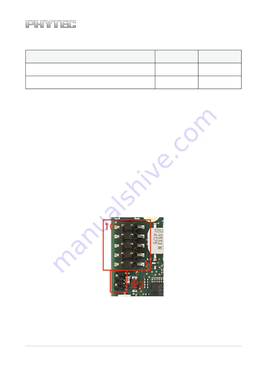
Jumper JP2 can be installed to add a 120 Ohm termination resistor across the CAN data lines if needed.
FIGURE 8: Components Supporting the CAN Interface
The table below shows the signal mapping of the CAN1 signals at connector X3.