background image


FASTCAM-512PCI 

Hardware Manual 


Rev.1.06E 


Содержание FASTCAM-512 PCI

Страница 1: ...FASTCAM 512PCI Hardware Manual Rev 1 06E...

Страница 2: ...is held by PHOTRON LIMITED Product specifications and manual contents are subject to change without notice PHOTRON LIMITED bears no responsibility for any results by using our products nor by applying...

Страница 3: ...vents immediately a task which has often proven difficult with conventional video systems You will find this new recording technology most useful to capture images of high speed subjects for subsequen...

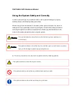
Страница 4: ...lained next Please pay careful attention to the content of the safety precautions when using the system This symbol indicates actions that carry the risk that a person could receive a serious injury T...

Страница 5: ...ects inside or pour liquids such as water on the system Doing so can cause fire electric shock or malfunction from short circuit or heat Do not disassemble or modify the system There are high voltages...

Страница 6: ...H or lower maximum altitude 2 000m or lower In addition if exceeding these limits use in a condensation free environment Doing so can cause malfunction Do not store the equipment in a location where t...

Страница 7: ...handling or cleaning the sensor Do NOT use a cleaning apparatus of electrostatic adsorption type electrified brush etc Discharge the human body static electrification before handling or cleaning work...

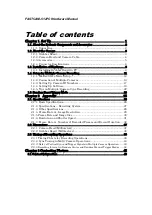
Страница 8: ...Reset Trigger Mode 23 Chapter 2 Appendix 25 2 1 Specifications 26 2 1 1 Basic Specifications 26 2 1 2 Specifications Recording System 27 2 1 3 Other Specifications 28 2 1 4 Frame Rate vs Image Resolut...

Страница 9: ...2PCI Hardware Manual 1 Chapter 1 Set Up 1 1 About the System s Components and Accessories 1 2 About the Camera 1 3 Installation of Hardware 1 4 Setup for Multiple Camera Recording 1 5 Random Reset Tri...

Страница 10: ...FASTCAM 512PCI Hardware Manual 2 1 1 About the System s Components and Accessories 1 1 1 Unpacking Refer to the attached packing list for this product s standard components and accessories...

Страница 11: ...t expose to liquids such as water Do not subject to excessive force 1 2 1 Grabber Board The grabber board of the FASTCAM 512PCI has been designed so that up to four FASTCAM 512PCI boards can be instal...

Страница 12: ...and compact structure specifically designed for easy handling in varied recording conditions It takes lenses of C type mount A tripod shoe groove is provided on each side of the camera Camera Connect...

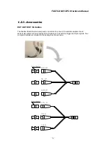
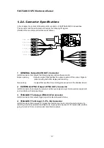
Страница 13: ...o compound connectors to connect it to external equipment and devices via cables to receive and send out signals such as external trigger and sync signals Two compound cables are included in the packa...

Страница 14: ...y and recording Rec pos neg A signal that specifies the recording process period of the Grabber Board 2 EXTERNAL SYNC Output SYNC OUT Connector A BNC connector that outputs the camera s vertical sync...

Страница 15: ...o send contact closure signals to control the start and end of a recording in currently selected recording mode To avoid possible damage to the camera system do NOT input signals other than contact cl...

Страница 16: ...T SW IN Input Circuit Note TRIGGER TTL IN works at the rising edge of the TTL signal and TRIGGER SW IN at the falling edge TRIGGER IN TRIGGER START 5V TTL level Photocoupler TLP521 TOSHIBA I O Port 33...

Страница 17: ...Remove covers of the PC following the PC s instruction manual 3 Make sure there are unused PCI slot s 4 Remove the metal cover plate in the back of the unused PCI slot where you wish to install the Gr...

Страница 18: ...cable connector shell to avoid damage to the system by an accidental disconnection during operation In case the board guide of the grabber board does not fit the slot readjust the guide board or remo...

Страница 19: ...rd a common subject from different perspectives along a shared timeline This capability can also be used to record images of a fast moving subject together with other subjects related to it from diffe...

Страница 20: ...he location of dipswitches as seen from above Setting Up Master Slave Mode Dipswitches Operate dipswitches to set up one board for master and the others for slave as shown in the following table Dipsw...

Страница 21: ...en boards as described in the following subsections Details of Connectors 1 GENERAL Output GEN OUT Connector 2 EXTERNAL SYNC Output SYNC OUT Connector 3 TRIGGER TTL Output TRIG OUT Connector 4 TRIGGER...

Страница 22: ...PCI R2 cameras Due to delay of signals between the boards Example 2 is recommended except for using software trigger see Section 3 3 Timing Charts Example 1 Basic Connection Good for software triggeri...

Страница 23: ...ecommended Connection The characteristic of the circuit configuration inside the 512PCI camera inevitably causes a slight error of 22 98 nsec against the input sync signal Example For 10 000 Hz input...

Страница 24: ...ggering only Trigger Generator PC 1 PC 2 Master Mode Slave Mode Slave Mode Slave Mode Camera ID 0 Camera ID 1 Camera ID 2 Camera ID 3 SYNC IN SYNC OUT TRIG OUT T TTL SW IN SYNC OUT TRIG OUT SYNC IN SY...

Страница 25: ...sed in a multiple camera system Dipswitch Operation to Set Up Camera ID Numbers Camera ID numbers 1 to 4 are defined by the ON OFF position of dipswitches 1 2 and 3 as shown below ID No Dipswitches SW...

Страница 26: ...low the below procedure to set up software For details of software operation see the Software User s Manual Setting Up Master Board For sync operation of multiple FASTCAM 512PCI cameras 1 Select the c...

Страница 27: ...FASTCAM 512PCI Hardware Manual 19 3 Select the desired polarity of sync signal from the SYNC OUT box The polarity of sync signal must match that selected for the slave board...

Страница 28: ...up more details 3 Select a mode of synchronization from the SYNC IN box Now this slave camera can be synchronized with and triggered by the master camera In other words this camera has been set up in...

Страница 29: ...er the ON OTHERS POS or ON OTHERS NEG synchronization mode is selected in the SYNC IN box for a slave camera this camera can be synchronized with and triggered by the master camera In other words this...

Страница 30: ...delay is inevitably caused between trigger and vertical sync signals while they are forwarded from board to board This delay may in rare cases result in an offset of one recorded image frame between...

Страница 31: ...describes how to do it Refer to the Software User s Manual for details of software operation 1 Press the Trigger Mode button 2 Select trigger mode as the Random Reset 3 Enter the desired number of fra...

Страница 32: ...FASTCAM 512PCI Hardware Manual 24 Memo...

Страница 33: ...FASTCAM 512PCI Hardware Manual 25 Chapter 2 Appendix 2 1 Specifications 2 2 Dimensions 2 3 Timing Charts...

Страница 34: ...2 Sensor Size 8 2mm 8 2mm Pixel Size 16 m x 16 m Sensor Type Color Bayer or Monochrome Lens Mount C mount Segmentation Available Electronic Shutter Available Camera Head Dimensions W 85 x D 65 x H 85...

Страница 35: ...rding Changes framing rate at an external timing signal from GENERAL IN Available rates 1 2 1 4 and 1 8 of set frame rate Standard Applied Rev2 1 Standard 5V 32bits 33MHz Board Size PCI Full size stan...

Страница 36: ...h a power source s independent from the currently used PC must be added as necessary Application Software and OS PFV Photron FASTCAM Viewer3 SDK compatible Windows 2000 Windows XP Windows Vista Memory...

Страница 37: ...able to each frame rate is shown in the below table Other resolutions may be selected from the list in subsection 2 1 5 Frame Rate Max Resolution pixels 60FPS 512 512 125FPS 512 512 250FPS 512 512 500...

Страница 38: ...00 1000 2000 4000 8000 16000 32000 512 512 NA NA NA NA 512 256 NA NA NA 512 128 NA NA 512 64 NA 512 32 256 512 NA NA NA NA 256 256 NA NA NA 256 128 NA NA 256 64 NA 256 32 128 512 NA NA NA NA 128 256 N...

Страница 39: ...1 8000 0 0001250000 1 57500 0 0000174632 1 8500 0 0001176471 1 60500 0 0000165441 1 9000 0 0001112132 1 64000 0 0000156250 1 9500 0 0001056985 1 68000 0 0000147059 1 10000 0 0001001838 1 72500 0 00001...

Страница 40: ...4 369 067 131 072 2 184 533 64 64 524 288 8 738 133 262 144 4 369 067 64 32 1 048 576 17 476 267 524 288 8 738 133 Frames Time sec Frames Time sec 512 512 8 192 65 536 4 096 32 768 512 256 16 384 131...

Страница 41: ...524 288 2 097 152 262 144 1 048 576 64 32 1 048 576 4 194 304 524 288 2 097 152 Frames Time sec Frames Time sec 512 512 8 192 16 384 4 096 8 192 512 256 16 384 32 768 8 192 16 384 512 128 32 768 65 5...

Страница 42: ...64 524 288 524 288 262 144 262 144 64 32 1 048 576 1 048 576 524 288 524 288 Frames Time sec Frames Time sec 512 512 8 192 4 096 4 096 2 048 512 256 16 384 8 192 8 192 4 096 512 128 32 768 16 384 16...

Страница 43: ...64 256 131 072 32 768 65 536 16 384 64 128 262 144 65 536 131 072 32 768 64 64 524 288 131 072 262 144 65 536 64 32 1 048 576 262 144 524 288 131 072 Frames Time sec Frames Time sec 512 512 512 256 5...

Страница 44: ...384 131 072 8 192 128 32 524 288 32 768 262 144 16 384 64 512 64 256 64 128 64 64 524 288 32 768 262 144 16 384 64 32 1 048 576 65 536 524 288 32 768 Frames Time sec Frames Time sec 512 512 512 256 51...

Страница 45: ...FASTCAM 512PCI Hardware Manual 37 2 2 Dimensions 2 2 1 Camera Head Millimeters 64 2 8 2 56 85 85...

Страница 46: ...2PCI Hardware Manual 38 312 98 5 22 95 87 70 106 5 Slide to adjust up to 12mm Board Guide 346 82 335 02 12 2 2 2 Grabber Board Millimeters Dimensions of Grabber Board Only Grabber Board Fitted with Bo...

Страница 47: ...low chart shows the temporal relationship between signals related to recording operation in START and RANDOM trigger modes random reset not effective The START trigger mode starts recording when a tri...

Страница 48: ...y the incoming trigger so that the timing of the incoming trigger signal and the start of exposure coincide more accurately as shown in the below chart The START trigger mode starts recording when a t...

Страница 49: ...dded to START and RANDOM trigger mode with Reset is in effect Note A shorter exposure period is set by the shuttering function in addition to the Expose pos signal being reset at the incoming trigger...

Страница 50: ...e above timing chart is for an End Trigger operation The CENTER trigger mode ends recording after filling the latter half of the available memory The MANUAL trigger mode records a preset number of fra...

Страница 51: ...n cameras involved in multiple camera operation To avoid this drawback other connection methods shown in 2 4 2 are recommended Delay time in camera 2 3 3 Delay of Vertical Sync and Trigger Signals in...

Страница 52: ...Manual modes because Center or Manual operation is repeatedly executed the following interval is necessary between one recording and next The interval can be checked by observing Rec Pos Neg signal on...

Страница 53: ...FASTCAM 512PCI Hardware Manual 45 Chapter 3 Contacting Photron 3 1 Contact Information...

Страница 54: ...al Condition of the system and what is known about it Contact Information In Americas and Antipodes PHOTRON USA INC 9520 Padgett Street Suite 110 San Diego CA 92126 4446 USA Phone 800 585 2129 or 858...

Страница 55: ...Printed in Japan Control No E180406U F FA AS ST TC CA AM M 5 51 12 2P PC CI I Hardware Manual Revision 1 06E US EU Publication Date April 2018 Publisher PHOTRON LIMITED 21F Jimbocho Mitsui Bldg 1 105...

Отзывы: