Copyright © 2011, PHONO SOLAR
Page 13 of 29
official or licensed professional engineer (see rack installation manual).
SELECTING THE PROPER MOUNTING STRUCTURE AND HARDWARE
Observe all instructions and safety precautions included with the mounting system
to be used with the module.
Do not drill holes in the glass surface of the module. Doing so will void the warranty.
Do not drill additional mounting holes in the module frame. Doing so will void the
Warranty.
Modules must be securely attached to the mounting structure using four mounting
points for normal installation. If heavy wind or snow loads are anticipated,
Additional mounting points should also be used. Please see the drawing below.
Load calculations are the responsibility of the system designer or installer.
The mounting structure and hardware must be made of durable, corrosion- and
UV-resistant material.
1. Mounting With Bolts
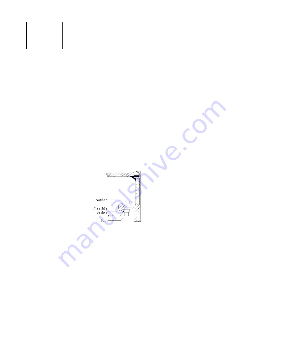
The frame of each module has 8 mounting holes (14mm*9mm) used to secure the
modules to supporting structure. The module must be attached and supported by at
least four
¢
8mm bolts through the indicated mounting holes, each connector using
stainless steel. See Figure 2 for each bolt Connection.
Figure 2
Flat washer with diameter of 8.5mm,flexible washer with diameter of 8.2mm.
If module clamps are used to secure the module, the torque on the clamp bolt
should be around 8
–10 Nm.
A minimum of four module clamps should be used, two on each long frame side,
in the general clamping areas denoted by the wide arrows on the drawing.
Depending on the local wind and snow loads, additional mounting points may be
required.
2. Other
Other mounting methods are acceptable as long as the minimum requirement
as described under 1.
To ensure that the module and the installation of at least 5cm distance.
Maximum loading capacity of the module for 30lb/ft ^ 2.


