background image


www.hartmann-electronic.com 


Rev. 1.2 

15 


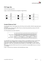
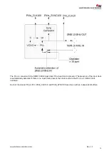
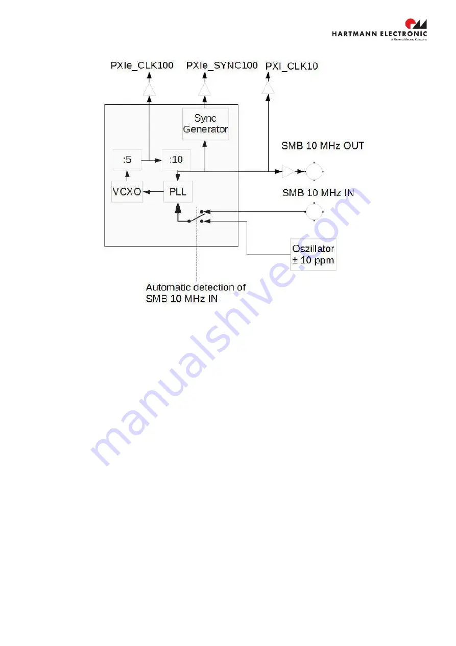
The PLL is connected to the SMB 10 MHz input clock if the input clock is present. The presence of the input clock 
is automatically detected. If there is no input clock present, the clock source to the PLL is a 10 MHz Clock 
oscillator.  
 
Each of the clocks PXI_CLK10, PXIE_CLK100, and PXIE_SYNC100 are driven with an independent buffers. 


Содержание HARTMANN ELECTRONIC PXCe4006 Series

Страница 1: ...www hartmann electronic com Rev 1 2 1 PXIe Chassis PXCe4006 6 Slot 1U 19 High Power Version User Manual...

Страница 2: ...er Supply Update 17 03 2020 J Brosowski Imprint Hartmann Electronic GmbH Motorstra e 43 D 70499 Stuttgart Weilimdorf Telephone 49 711 1 39 89 0 Telefax 49 711 8 66 11 91 E Mail info hartmann electroni...

Страница 3: ...t Panel LEDs 16 Interoperability with CompactPCI 16 3 Installation 17 Connecting Chassis Grounding 17 Inspecting the Chassis Components 17 Protection Against Electromagnetic Interference 17 Installing...

Страница 4: ...www hartmann electronic com Rev 1 2 4 PXIe Peripheral Slot 35 8 Ordering Information 36...

Страница 5: ...untry in which it will be used Safety Symbols Hazardous voltage Familiarise yourself with the danger of electrical voltages and the safety precautions before starting to work with parts that carry dan...

Страница 6: ...rostatic Discharge Precautions Electronic components can easily be destroyed by electrostatic discharge which can occur between chassis components and a person Before working on the chassis make sure...

Страница 7: ...properly grounded at all times the following conditions shall be met This equipment shall be connected directly to the AC supply system earth ground Board Installation Electrostatic discharge and inc...

Страница 8: ...h PXI and PXI Express The key features of the PXCe4006 Series Chassis include the following Optional Rear Panel PXI_TRIG 7 0 SMB I O Connector Rear Panel PXI_CLK10 I O Connector Removable Fan Tray to...

Страница 9: ...com Rev 1 2 9 Chassis Description Figure 2 1 Front view of the PXCe4006 series Chassis 1 System slot 5 Power LED 2 PXIe peripheral slot 6 On Standby momentary power switch 3 PXIe hybrid slots 7 Remov...

Страница 10: ...ry switch 6 at the front Panel Position 2 Fan Control The Chassis cooling fans are running at full speed Fan control is enabled Fan Control The Chassis Cooling Fans are controlled through two temperat...

Страница 11: ...www hartmann electronic com Rev 1 2 11...

Страница 12: ...thout the momentary switch on the front panel Therefore the auto mode of the chassis has to be turned on The auto mode can be turned on by changing the DIP Switch s position 1 on the chassis rear pane...

Страница 13: ...slot using PCIe X1 These slots have up to 500MB s single direction dedicated bandwidth X1 Gen 2 PCI Express PXI Local Bus The PXIe backplane local bus is a daisy chained bus that connects each periphe...

Страница 14: ...s are as shown in Figure 2 6 The PXCe4006 Series Chassis provides an external 10 MHz PXI_CLK10 SMB Clock input If a Clock signal is detected on the rear panel SMB connector the backplane automatically...

Страница 15: ...clock if the input clock is present The presence of the input clock is automatically detected If there is no input clock present the clock source to the PLL is a 10 MHz Clock oscillator Each of the c...

Страница 16: ...teroperability with CompactPCI The PXCe4006 series chassis allows you the flexibility to use the following devices in a single PXI Express system PXI Express compatible products CompactPCI Express com...

Страница 17: ...e is a 4 mm stud on the rear panel This stud is only for potential equalization Proper grounding is achieved through the protective earth conductor of the power cable Inspecting the Chassis Components...

Страница 18: ...ce connector pins 5 Install filler panels in unused or empty slots Filler panels consists of a front panel with or w o air baffles EMC gasket and mounting screws WARNING Close all empty chassis slots...

Страница 19: ...recommended that the NI PXI Platform Services is installed before the Hartmann Electronic installer is executed Make sure that the installer is executed within its original folder location After runni...

Страница 20: ...the shelf until the interface connector disengages Wait until the fans have stopped and then remove the fan tray from the shelf WARNING Extreme care should be taken while handling the fan tray It is r...

Страница 21: ...ing to EN 60950 1 HARTMANN PXCe4006 Series Chassis are not end products with independent functionality according the EMC regulations therefore CE marking is not required Not before CPCI PXI Express bo...

Страница 22: ...upply Main Power EFORE RCB600 AABB Power available for Backplane Table 6 2 shows the available Power over the specified operating temperature Range Voltage Maximum Current Maximum Power 5V AUX 2 A 10...

Страница 23: ...55 PXIe_SYNC100 Maximum slot to slot skew 100 ps Accuracy 25 ppm Duty factor 45 55 External PXI_CLK10 output SMB Rear panel connector Frequency 10 MHz 25 ppm Accuracy 25 ppm Output Impedance 50 10 Ext...

Страница 24: ...ion results each slot is equipped with a load card Each load card has a mounted heat sink That reduces the air flow that is pushed from the fan tray through the modules The resulting lack of air flow...

Страница 25: ...hassis The graph results out of an operating temperature range of 50 C Each Load card is configured to produce a heat dissipation of 40 W Slot As shown in the graph the maximum temperature in the heat...

Страница 26: ...26 1 IEC 61326 1 Class A emission EN 55011 CISPR 11 Group 1 Class A emission EN 55022 CISPR 22 Class A emission EN 55024 CISPR 24 Immunity AS NZS CISPR 11 Group 1 Class A emission AS NZS CISPR 22 Clas...

Страница 27: ...tronic com Rev 1 2 27 Mechanical Chassis weight ca 6 kg Figure 6 1 PXCe4006 series Chassis Dimensions Front Dimensions are in Millimeter Figure 6 2 PXCe4006 series Chassis Dimensions Side Dimensions a...

Страница 28: ...www hartmann electronic com Rev 1 2 28 Figure 6 3 PXCe4006 series Chassis Dimensions Bottom Dimensions are in Millimeter...

Страница 29: ...gure 6 4 shows the recessed mounting equipment for the chassis The equipment allows the chassis to be mounted recessed into a 19 Rack The depth of the chassis in the rack can be adjusted through the m...

Страница 30: ...he system make sure that all slots are populated with either boards or filler panels Chassis Material 1 0330 st12 03 ZE Humidity Operating 5 to 80 non condensing Storage 5 to 80 non condensing Tested...

Страница 31: ...Assignment The Pin assignment applies with the PXI 5 PXI Express Hardware Specification and the CompactPCI PICMG 2 0 R 3 0 specification System Controller Slot 4 Link Configuration PXI Express Hybrid...

Страница 32: ...5 1PETp0 1PETn0 GND 1PERp0 1PERn0 GND 1PETp1 1PETn1 GND 6 1PETp2 1PETn2 GND 1PERp2 1PERn2 GND 1PERp1 1PERn1 GND 7 1PETp3 1PETn3 GND 1PERp3 1PERn3 GND 2PETp0 2PETn0 GND 8 2PETp1 2PETn1 GND 2PERp1 2PER...

Страница 33: ...ND RSV PXI_LBL6 PXI_LBR6 GND Pin A B ab C D cd E F ef XP3 Connector 1 PXIe_CLK100 PXIe_CLK100 GND PXIe_SYNC100 PXIe_SYNC100 GND NC NC GND 2 PRSNT PWREN GND NC NC GND NC NC GND 3 SMBDAT SMBCLK GND RSV...

Страница 34: ...R C BE 1 GND 17 GND 3 3V IPMB_SCL IPMB_SDA GND PERR GND 16 GND DEVSEL GND V I O STOP LOCK GND 15 GND 3 3V FRAME IRDY BD_SEL TRDY GND 12 14 Key Area 11 GND AD 18 AD 17 AD 16 GND C BE 2 GND 10 GND AD 21...

Страница 35: ...PXI_LBL6 PXI_LBR6 GND Pin A B ab C D cd E F ef XP3 Connector 1 PXIe_CLK100 PXIe_CLK100 GND PXIe_SYNC100 PXIe_SYNC100 GND NC NC GND 2 PRSNT PWREN GND NC NC GND NC NC GND 3 SMBDAT SMBCLK GND RSV RSV GND...

Страница 36: ...www hartmann electronic com Rev 1 2 36 8 Ordering Information Ordering Number Description PCI V I O LMH0000910 PXI Express 6 Slot 1U Chassis HiPow 5 V...

Отзывы: