background image

ENVIRO 6 SLIDING GATE OPERATOR 


buttons or three buttons together, but you need repeat the program/learn process if you want to use 

more than one button. 
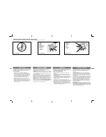


Fig.12

 Remote transmitter


  Adding extra remote controls (Learn):


Remove the cover, press the learn button  AN1  (Fig.8), then 

the 

2 (Fig.8) will be on and turn off, then press the remote control button which you want to use, 

the  LED

  LED

2  will turn on about 2 seconds and then turn off again. The learning process is finished. 

Up to 25 remote controls may be used. 

  Erase remote controls: To erase all existing remote controls, press and hold learn button  AN1 , the   

LED2  turns on, release  the button once  LED2  turns off. This indicates that  all the remote 

controls have been erased completely. 


Note

: Press the  OPEN  button of external button switch or remote control button which has been 

learned, the gate will open, the motor rotates clockwise, and the  LED2     is turns on. The output 

voltage between  D1 and D2  (terminal X3) is AC220V, the voltage between  V  and  U  is AC220V

.Press  STOP  button or the same remote control button, the gate stops running. And the  LED2  

  is turns off. Then press  CLOSE  button or the same remote control button again, the gate will close, 

the motor rotates anticlockwise, and the  LED2  is turns on. The output voltage between  D1 and D2  

(terminal X3) is AC220V, the voltage between  V  and  W  is AC220V . Press the  STOP  button or 

the same remote control button, the gate stops running. And the  LED2  is turns off. 


Verify open direction: If the gate does not move in the desired direction, then you will need to 

reverse the motor operating direction, open the black plastic cover, you can do this by exchanging

 wires  U  and  

OPLT  and  CLLT . 


Button 1

Button 2

Button 3

Button 4

Содержание Enviro 6

Страница 1: ...Sliding Gate Operator User s Manual ENVIRO 6 http www phoenixgaragedoors com au P ...

Страница 2: ... 2 2 Important safety precautions 2 3 Main technical parameters 2 4 Mechanical Installation 2 5 Adjustment 5 6 Wire Connecting 6 7 Turning and operation 8 8 Programming Process 10 9 Maintenance 11 10 Trouble Shooting 11 11 Packing list 11 12 Warranty Registration 12 ...

Страница 3: ...3 Main technical parameters Type ENVIRO 6 Power supply 220V 50Hz Motor speed 42rpm Rated output power of motor 150W Remote control operating distance 30m Frequency 433 92mHz Remote control mode Single button Output shaft height 58 5mm Max gate weight 500Kg Output torque 14N m Limit switch Spring limit switch Noise 60dB Duty cycle S2 15 minutes extra remote control 20 Environmental temperature 2 C ...

Страница 4: ...concrete when it is poured Wires within the conduit shall be located or protected so that no damage can result from contact with any rough or sharp part Concrete pad The base unit of the gate operator requires a concrete pad in order to maintain proper stability The concrete pad should be approximately 400mm x 250mm x 200mm deep in order to provide for adequate weight and structure to insure prope...

Страница 5: ... insert the cover Check the operator and make sure it is lined up with the gate Fig 3 Installation of Rack l Fix the three nuts in the same package with rack on the rack element l Lay the first piece of rack on the gear and affix the first nut on the gate l Move the gate manually checking if the rack is resting on the gear and affix the second and third nut l Bring another rack element near to the...

Страница 6: ...ils must be installed horizontally Install the limit block as shown in Fig 4 and Fig 5 The spring limit switch and blocks are used to control the position of the gate Release the gear with the key and push the sliding gate manually to pre determine the position fix the block to the rack and lock the gear by push up the release bar Moving the gate electrically adjust the block to the proper positio...

Страница 7: ...ar Note Do not exceed 90 be careful not to use too much force otherwise the release bar will be damaged l Open and close the gate manually Note If the gate bumps the mounting post and cannot be electric opened move the gate a few inches by hand thus you can release the gate with the key open and close the gate manually Fig 7 6 Wire Connecting Make sure that the power is OFF before making any elect...

Страница 8: ...1 and D2 terminal X3 ENVIRO 6 AC220V c Output power supply 24VDC COM COM I R N C Infrared If the infrared beam is interrupted during closing the gate will reverse and open immediately The product is not factory equipped with an infrared device the infrared output signal must be N C GND 24VDC Out I R COM 24VDC Terminal X2 Infrared Control board Infrared with DC input Signal ...

Страница 9: ...common wire of switch to COM Common Stop Close Open Three button switch COM COM Control board terminal block Control board terminal block Single button switch Keypad OPN CLS STP OPN CLS STP terminal X4 terminal X4 Fig 10 Motor and capacitor Terminal X2 X3 V com U Positive direction W Opposite direction E grounding C capacitor Control board C C Capacitor Terminal X3 W U V Motor W V U E Terminal X2 ...

Страница 10: ...tton of external button switch or remote control button which has been learned the gate will open the motor rotates clockwise and the LED2 is turns on The output voltage between D1 and D2 terminal X3 is AC220V the voltage between V and U is AC220V Press STOP button or the same remote control button the gate stops running And the LED2 is turns off Then press CLOSE button or the same remote control ...

Страница 11: ...ice responds to your expected function 2 If the gate can not be moved please check whether the gate is obstructed or the gate is too weight Activities Covered in this section l Remote transmitter With each press of the button the gate will close stop open or stop cycle Single button mode l Three button mode external button switch not supply press OPEN button the gate opens Press STOP button the ga...

Страница 12: ...m mains supply before replacing bulb l Be sure to read the entire manual before attempting to perform any installation or service to the door operator l Our company reserves the right to change the design and specification without prior notification 10 Troubleshooting Trouble Possible causes Solutions The door fails to open and close LED display does not light 1 Power is OFF 2 Fuse burn 1 Make sur...

Страница 13: ...tem Quantity 1 ENVIRO 6 sliding gate operator 1 2 Transmitter 2 3 Release key 2 4 User s manual 1 12 Warranty Registration For your operator warranty registration please visit our website www phoenixgaragedoors com au warranty registration ...

Отзывы: