Installation
4109_en_B
PHOENIX CONTACT
9/28
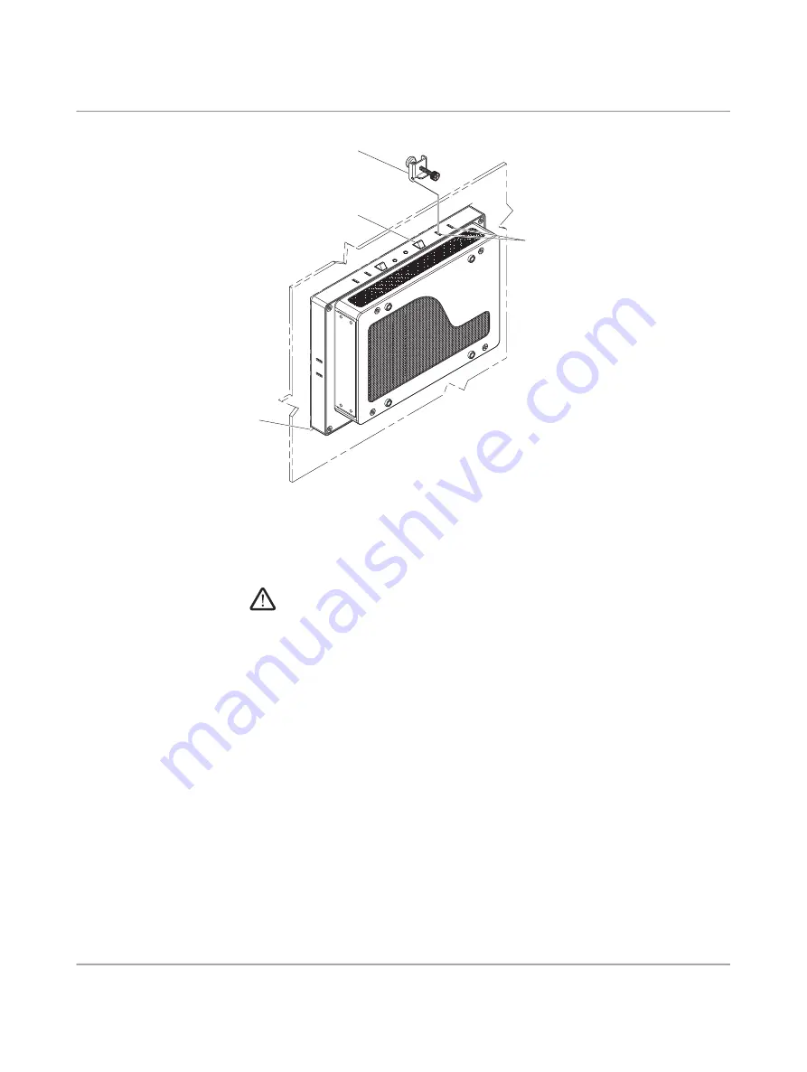
Figure 3
-
2
Panel mounting clamps
2. From the front, place the bottom edge of the TP 6…PS in the opening (1), making sure
the spring-loaded retention clips (2) are inside the panel. Tilt the top of the TP 6…PS
into the opening until the retention clips are inside the panel. Ensure that the gasket is
properly positioned in the groove and against the panel.
CAUTION:
All clamps must be installed around the display to secure the TP 6…PS in the panel.
The retention clips on top and bottom of the monitor only provide temporary assis
-
tance during installation.
3. From the rear, place the clamps (3) in the slots (4) on the display. Clamps must be in
-
stalled in every slot.
4. Tighten the screws on all clamps, alternating from one side to the other until the front
bezel is secure against the mounting panel. Torque the screws to 0.78 Nm.
Removal
1. Remove power and disconnect cables to the TP 6…PS.
2. Loosen and remove the clamps securing the TP 6…PS in the panel.
3. Using an assistant, press the retention clips along the top, and tilt the TP 6…PS for
-
ward.
4. Lift the TP 6…PS so the bottom retention clips clear the panel, and remove.
2
3
4
1
Содержание TP 6000 HMI
Страница 1: ...User manual UM EN TP 6000 TP 6000 HMI for machine control...
Страница 4: ...TP 6 PS 2 28 PHOENIX CONTACT 4109_en_B...
Страница 8: ...TP 6 PS 6 28 PHOENIX CONTACT 4109_en_B...
Страница 16: ...TP 6 PS 14 28 PHOENIX CONTACT 4109_en_B...
Страница 18: ...TP 6 PS 16 28 PHOENIX CONTACT 4109_en_B...
Страница 26: ...TP 6 PS 24 28 PHOENIX CONTACT 4109_en_B...
Страница 28: ...TP 6 PS 26 28 PHOENIX CONTACT 4109_en_B...


