


5756B
19
Integration of the Controller Board in
STEP 7
®
Integrate the controller board as a standard SIMATIC
®
component (FM 353 for Step Motor, S7 FM-POS).
To create the hardware configuration, select one of the
following two options:
–
Reading out the PLC configuration
–
Linking the controller board manually
Reading Out the PLC Configuration
1. Start the STEP 7
®
SIMATIC
®
software.
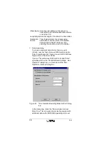
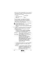
2. In the "PLC" menu, select the "Display Accessible Nodes"
option using the mouse. Then you can choose the MPI
address for the CPU.
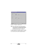
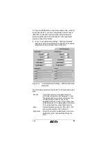
3. In the "PLC" menu, select the "Diagnose Hardware"
option.
After reading out the PLC configuration, the
IBS S7 300 DSCT controller board now declares itself as
S7 FM-POS (FM 353 for Step Motor) in the analog area with
16 byte inputs/outputs.
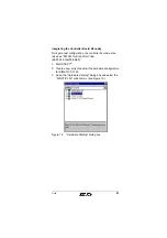
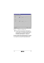
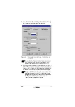
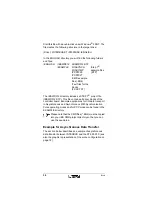
4. In the "Hardware Configuration" window, double-click with
the left mouse button on the "FM 353 for Step Motor" item.
This opens the "Properties - FM 353 Step ..." dialog box
(Figure 18).
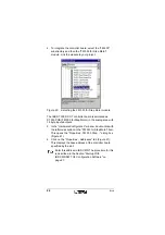
5. Click on the "Properties... Addresses" tab (Figure 18).
This displays the base address of the controller board
specified by the slot.
Enter this address in IBS CMD. The procedure for this
is described in the section "Startup With
IBS CMD SWT G4 Configuration Software" on
page 27.


