background image

IB IL 24/230 DOR 4/W-PC (-PAC)

4

6530B

General Description

Figure 2

IB IL 24/230 DOR 4/W-PC 
with an appropriate connector

Function Identification

Red with lightning bolt

Housing/Connector Color

Gray housing

Gray connector

Local LED Diagnostic and Status Indicators

Terminal Assignment for Each Connector

In the corresponding connector IB IL SCN-8-AC-REL, 
the adjacent contacts
1.2/2.2, 1.3/2.3, and 1.4/2.4 are jumpered.

It is therefore possible to transmit the power to 
supply several relays of IB IL 24/230 DOR 4/W-PC 
terminals from one connector to the next via a 
jumper.

1

2

1

2

3

4

1

2

3

4

1 . 1

1 . 2

1 . 3

1 . 4

2 . 1

2 . 2

2 . 3

2 . 4

6 5 3 0 A 0 0 3

1

2

D

D O R 4 / W

3

4

Des.

Color Meaning

D

Green Diagnostics

1, 2,

3, 4

Yellow Output status indicator

(relay has picked up)

Terminal 
Points

Assignment

1.1, 2.1

Not used
(no contact present)

1.2, 2.2

Relay N/C contact

1.3, 2.3

Relay main contact

1.4, 2.4

Relay N/O contact

Please note that the current at one 
terminal point must not exceed 8 A.

Содержание IB IL 24/230 DOR 4/W-PC

Страница 1: ...The IB IL 24 230 DOR 4 W PC and IB IL 24 230 DOR 4 W PC PAC only differ in the scope of supply see Ordering Data on page 17 Their function and technical data are identical For greater clarity the Orde...

Страница 2: ...who are able to recognize and avoid any possible dangers Definitions for skilled workers according to EN 50110 1 1996 The instructions given in the IB IL SYS PRO UM E User Manual or the Inline System...

Страница 3: ...the segment in which the terminal is located e g switching 230 V AC within a 24 V DC segment In this case place a distance terminal before and after the IB IL 24 230 DOR 4 W PC terminal see Ordering D...

Страница 4: ...3 2 3 and 1 4 2 4 are jumpered It is therefore possible to transmit the power to supply several relays of IB IL 24 230 DOR 4 W PC terminals from one connector to the next via a jumper 1 2 1 2 3 4 1 2...

Страница 5: ...conditioning LED Terminal point without metal contact Relay FE or PE depending on the area in which the terminal is used Electrically isolated area I O area including relay contact isolated from the l...

Страница 6: ...ay contacts 1 2 1 2 3 4 1 2 3 4 1 2 1 2 3 4 1 2 3 4 1 2 1 2 3 4 1 2 3 4 1 2 1 2 3 4 1 2 3 4 1 2 D D O R 4 W 3 4 6 3 2 6 A 0 0 5 1 2 3 4 N C c o n t a c t M a i n c o n t a c t N O c o n t a c t N C c...

Страница 7: ...4 1 6 3 2 6 A 0 0 6 1 2 1 2 3 4 1 2 3 4 1 2 1 2 3 4 1 2 3 4 1 2 D D O R 4 W 3 4 1 2 1 2 3 4 1 2 3 4 1 2 1 2 3 4 1 2 3 4 1 2 1 2 3 4 1 2 3 4 1 2 1 2 3 4 1 2 3 4 1 2 1 2 3 4 1 2 3 4 3 2 1 2 1 2 3 4 1 2...

Страница 8: ...following protective circuits can be used Contact protective circuit Load protective circuit Combination of both protective circuits Figure 8 Contact protective circuit A load protective circuit B If...

Страница 9: ...t o r H i g h d e l a y N o A d v a n t a g e s U n c r i t i c a l s i z i n g D i s a d v a n t a g e s A t t e n u a t i o n o n l y a b o v e U Z D Y e s A d v a n t a g e s C o s t e f f e c t i...

Страница 10: ...i n a t i o n D i s a d v a n t a g e s E x a c t d i m e n s i o n r e q u i r e d H i g h i n r u s h c u r r e n t Capacitor C LLoad 4 RLoad 2 Resistor R 0 2 RLoad P r o t e c t i n g t h e l o a...

Страница 11: ...missible alternating current This maximum direct current value is also highly dependent on the voltage and is determined in part by design conditions such as the contact distance and contact opening s...

Страница 12: ...n data of other bus systems please refer to the appropriate electronic device data sheet GSD EDS Byte bit view Bit 0 3 0 2 0 1 0 0 Assignment Slot 4 3 2 1 N C contact 1 2 1 2 1 2 1 2 Main contact 1 3...

Страница 13: ...t 70 kPa to 106 kPa up to 3000 m 9843 ft above sea level Degree of protection IP 20 according to IEC 60529 In the range from 25 C to 55 C 13 F to 131 F appropriate measures against increased humidity...

Страница 14: ...lamp loads and capacitive loads 6 A for T 200 s Nominal power consumption of the coil at 20 C 68 F 330 mW from the 7 5 V supply Resistance of the coil at 20 C 68 F 119 12 Maximum switching frequency w...

Страница 15: ...hing Voltage V DC Switching Current A 5 3 0 10 3 0 20 3 0 30 3 0 40 1 0 50 0 4 60 0 3 70 0 26 80 0 23 90 0 215 100 0 2 150 0 18 200 0 165 250 0 155 Load Current IL in A as a Function of the Switching...

Страница 16: ...ssipation of the relay coil PL Power dissipation through the load current via the contacts IL Load current of the output Power Dissipation of the Housing Depending on the Ambient Temperature PHOU 2 7...

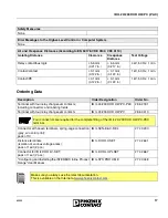
Страница 17: ...connectors and labeling fields IB IL 24 230 DOR 4 W PC PAC 28 62 18 1 Terminal with four relay changeover contacts IB IL 24 230 DOR 4 W PC 28 60 41 3 Connector with seven terminals spring cage connect...

Страница 18: ...x Contact 03 2003 Technical modifications reserved TNR 90 11 32 6 Phoenix Contact GmbH Co KG Flachsmarktstr 8 32825 Blomberg Germany 49 52 35 30 0 49 52 35 34 12 00 www phoenixcontact com Worldwide Lo...

Отзывы: