


Installation
4024_en_E
PHOENIX CONTACT
3.2
Interfaces
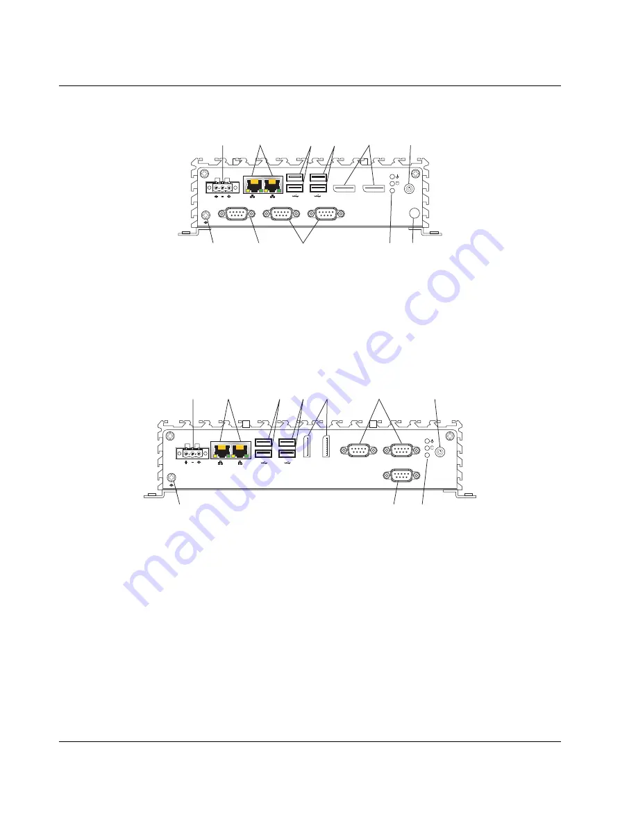
Figure 3-6
Connectors and ports (BL2 … 1100, BL2 … 2100)
Figure 3-7
Connectors and ports (BL2 … 3100, BL2 … 7100, BL2 … 9100)
After mounting the BL2 ...100, make any necessary cable connections (see Figure 3-6).
The available connectors are:
–
Ethernet (ETH): Two RJ45 connectors allow the computer to communicate on a
10/100/1000 Base-T Ethernet network.
–
Serial (COM): Three D-SUB 9 serial ports are available for use. Two ports are set as
RS-232 while one port is configurable as either RS-232, RS-422, or RS-485.
1
Functional earth (ground) screw
2
Power connector
3
Ethernet RJ45 ports
4
USB 3.0 connectors
5
USB 2.0 connectors
6
DisplayPort connectors
7
On/off switch
8
Configurable RS-232/422/485 serial port
9
RS-232 serial ports
10
Status LEDs
11
Antenna mount location (optional)
DC24V
RS-232/422/485
1
2
SS
RS-232
RS-232
DP2
DP1
PG
2
3
4
5
6
9
10
7
11
8
1
1
Functional earth (ground) screw
2
Power connector
3
Ethernet RJ45 ports
4
USB 3.0 connectors
5
USB 2.0 connectors
6
DisplayPort connectors
7
RS-232 serial ports
8
On/off switch
9
Configurable RS-232/422/485 serial port
10
Status LEDs
Antenna mount location (optional) (see
DC24V
RS-232/422/485
1
2
SS
RS-232
RS-232
DP1
DP2
PG
2
1
3
4
5
6
7
8
9
10
Содержание Basicline 2 Series
Страница 1: ...User manual UM EN BL2 100 Basicline 2 configurable industrial PCs...
Страница 4: ...BL2 100 2 36 PHOENIX CONTACT 4024_en_E...
Страница 18: ...BL2 100 16 36 PHOENIX CONTACT 4024_en_E...
Страница 32: ...BL2 100 30 36 PHOENIX CONTACT 4024_en_E...
Страница 34: ...BL2 100 32 36 PHOENIX CONTACT 4024_en_E...
Страница 36: ...BL2 100 34 36 PHOENIX CONTACT 4024_en_E...


