


Page 18
5.3.4.3 Changing the scaling slope
Menu <–> Selection
use the current scaling slope
5.5 Monitoring parameter
21
Setting the scaling slope
5.4 Monitoring parameter
18
➱
➱
When the input signal exceeds the value
set here, than
is displayed.
Over-range: When the value exceeds
109 mV then
is displayed.
Menu <–> Selection
Example: 80.000
Select digit
Set digit
Upper limit
5.4 Setting the Scaling Slope
At least two points (2 pairs of values) are
required for the start point and end point of
the scaling slope. This slope can be rising
or falling. A maximum of 24 scaling points
can be used.
However it should be noted that in all
cases, whether the slope rises or falls, the
values that are inputted (Inp.01 … InP.24)
must increase sequentially.
The scaling slope must lie within the limits
of the input and display ranges. The first
and last points can lie on the limits.
press key
to accept the selection
press key
to accept the selection
Page 19
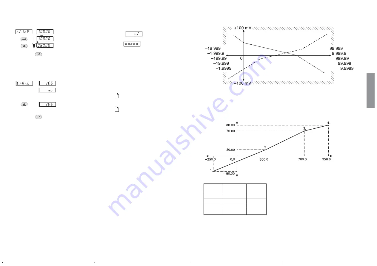
Input range –100 ... +100 mV
Display range
Example with 4 scaling points
Input range –100 ... +100 mV
knee
input-
display
points
value
value
1
–50,000
–250,0
2
20,000
300,0
3
70,000
700,0
4
80,000
950,0
It is recommended to note down the
required pairs of values for the sca-
ling points of the slope before star-
ting the set-up.
We will use this example in the following
pages
english


