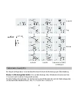


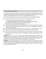


Connecting and Grounding
The controller is intended for indoor use only. Protect it from direct sunlight and place it in a dry
environment. Never install it in humid rooms (like bathrooms). The controller warms up during
operation, and should therefore be installed on a non flammable surface only.
Connect the controller by following the steps described below to avoid installation faults.
Observe the following connection sequence when installing the system:
1. Connect the battery to the charge controller – plus and minus.
2. Connect the photovoltaic modules to the charge controller – plus and minus.
3. Connect the load to the charge controller – plus and minus.
Follow the reverse procedure when uninstalling!
To avoid any voltage on the wires, first connect the wire to the controller, then to the
battery and to the photovoltaic modules. But for the load, first connect the wire to the
load, then to the controller.
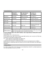
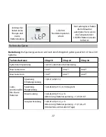
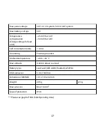
Recommended minimum wire size: CXup 10 : 4 mm
2
; CXup 20 : 6 mm², CXup 40 : 10 mm²
Make sure the wire length between battery and controller is as short as possible.
Be aware that all positive connections of the CXup controller are common and therefore
have the same electrical potential. If any grounding is required, always do this on the
positive wire.
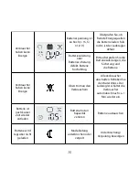
REMARK:
If the device is used in a vehicle whose battery negative pole is connected to the
chassis, please make sure that none of the loads connected to the controller has an electric
connection to the car body. Otherwise the load will be short circuited, thus affecting the Low
Voltage Disconnect function and the electronic fuse function of the controller.
REMARK:
Mind the recommendations of your battery manufacturer. We strongly recommend
connecting a fuse directly to the battery to protect any short circuit at the battery wiring. The
fuse must correspond to the nominal current of the charge controller: 15A for CXup 10 , 30A for
CXup 20 and 50A for CXup 40.
23
Содержание CXup 10
Страница 6: ...4 USB Ladeanschluss Schnittstelle f r den MXI MXI232 Adapter Temperatursensor f r den NTC Sicher ung...
Страница 14: ...12...
Страница 26: ...24 USB charging connector Interface for MXI MXI232 Temperature sensor NTC connector...
Страница 33: ...31...
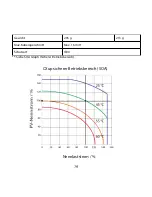
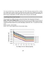
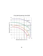
Страница 40: ...38 CXup Safe Operating Area SOA...
Страница 45: ...43 Conector USB de carga Interfaz para MXI MXI232 Sensor de temperatura Conector NTC Fusi ble...
Страница 53: ...51...
Страница 61: ...59 Zona de funcionamiento seguro de CXup SOA Corriente nominal de los consumidores...
Страница 66: ...64 Connecteur de chargement USB Interface pour MXI MXI232 D tecteur de temp rature du connecteur NTC Fusi ble...
Страница 74: ...72...
Страница 82: ...80 Aire de s curit CXup SOA Courant nominal charge...
Страница 87: ...85 Carregador via conector USB Interface para MXI MXI232 Sensor de temperatura Conector NTC Fus vel...
Страница 95: ...93...
Страница 102: ...Veja o gr fico da SOA rea de prote o segura 100 CXup rea de prote o segura SOA Corrente de carga nominal...
Страница 104: ...CXup LCD PWM USB MP3 CXup GEL AGM LiFePO4 12 24 V 1 5 LiFePO4 BMS 102...
Страница 105: ...CE CE 12 V 24 V 103...
Страница 106: ...1 2 3 CXup 10 4 mm2 CXup 20 6 mm CXup 40 10 mm CXup 1 5 CXup 10 15 A CXup 20 30 A CXup 40 50 A 104...
Страница 107: ...105 NTC MXI232 MXI USB...
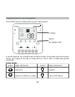
Страница 108: ...12 V 24 V 18 V 24 V LCD 106...
Страница 109: ...107 LCD ESC DOWN UP SET...
Страница 110: ...LVD C PWM SET DOWN UP 108...
Страница 111: ...90 70 90 30 70 10 30 0 10 0 25 1 109...
Страница 114: ...112...
Страница 115: ...1 2 3 4 50 V 50 V 15 5 31 0V 1 2 4 6 3 4 150 2 Min 200 3 s 113...
Страница 116: ...USB USB 5 V 1500 mA MXI MXI232 CXLink CXup MXI MXI232 PC CXlink CXup 2 CXlink CXlink NTC CXup 114...
Страница 117: ...15 5 31 0 V 1 115...
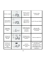
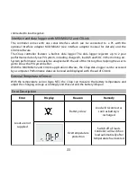
Страница 118: ...C Err NTC 116...
Страница 121: ...119 CXup SOA...
Страница 122: ...20160518 Phocos AG Germany www phocos com 120 ISO9001 RoHS...


