


55
To trunk output (11)
Vehicle trunk
release selenoid
Figure 8. The trunk release wiring
Control unit of
Pager or GSM gate
To PAGER output (9)
output is connected to
ground when is activated
Figure 9. The PAGER output wiring
+12V
+12V
T
o
s
ig
n
al
li
g
h
ts
o
u
tp
u
t
(1
2,
13
)
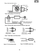
Common input (6)
connect on Ground
T
o
s
ig
n
al
li
g
h
ts
o
u
tp
u
t
(1
2,
13
)
Common input (6)
connect on +12V
+12V
Figure 7. Signal lights connecting example
To Start wire
To ACC or +12V
87
30
87a
85
86
Start
On
ACC
Off
Figure.5 Wiring diagram for start kill relay
Relay is delivered with alarm.
To output start kill (8)
To ignition input (10)
EN
EN
EN
EN
Figure. 6 Parking Lights output connected to the Hazard light switch
Lights Control Unit
Relay contact bypassing
the hazard light switch
Light output (12 or 13)
Common input (6)
Hazard
Lights
Switch
Vehicle Signal Light