background image


Instructions for Use | Introduction 


Trilogy Evo Universal Instructions for Use 


For Technical Support and Customer Service, contact Philips Customer Service:  

USA 

Respironics Inc. 

1001 Murry Ridge Lane Murrysville, PA   15668 


Email: 

[email protected]

[email protected]


Web: 

www.philips.com\healthcare


Authorized European Representative:  

Respironics Deutschland GmbH & Co. KG 

Gewerbestrasse 17 

D-82211 Herrsching Germany 

+49 8152 93060 


Copyright © 2018 Koninklijke Philips N.V.  All rights reserved. 

This work is protected under Title 17 of the United States copyright code and is the sole property of Philips Respironics.  No part 
of this document may be copied or otherwise reproduced, or stored in any electronic information retrieval system, except as 
specifically permitted under United States copyright law, without the prior written consent of Philips Respironics. 


Trilogy Evo Universal is the registered trademark of Respironics Inc. 

The Bluetooth® word mark and logos are registered trademarks owned by Bluetooth SIG, Inc. and any use of such marks by 
Philips Respironics is under license.  

Dawn Ultra is a registered trademark of Procter & Gamble.  

Other trademarks and trade names are those of their respective owners. 


Illustrations and screen images in this document are representative depictions. 


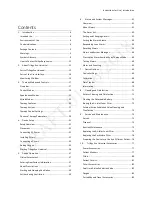
Содержание Trilogy Evo Universal

Страница 1: ...ates copyright code and is the sole property of Philips Respironics No part of this document may be copied or otherwise reproduced or stored in any electronic information retrieval system except as specifically permitted under United States copyright law without the prior written consent of Philips Respironics Trilogy Evo Universal is the registered trademark of Respironics Inc The Bluetooth word ...

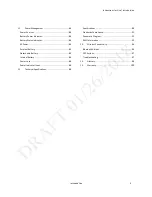
Страница 2: ...ing Ventilation 39 6 Alarms and System Messages 41 Overview 41 About Alarms 41 The Alarm List 42 Setting and Changing Alarms 42 Setting the Alarm Volume 43 Responding to an Alarm 43 Resetting Alarms 43 Alarms and System Messages 44 Prescription Alarm Availability by Therapy Mode 60 Testing Alarms 60 Alarm and Event Log 63 7 Device Options 65 Device Settings 65 Calibration 66 Data Transfer 68 Infor...

Страница 3: ... 84 AC Power 84 External Battery 85 Detachable Battery 85 InternalBattery 86 Power Loss 86 Power Indicator Icons 86 12 Technical Specifications 88 Specifications 88 Standards Compliance 91 Pneumatic Diagram 92 EMC Information 92 13 Wireless Connectivity 96 Bluetooth Actions 96 NFC Actions 97 Troubleshooting 97 14 Glossary 98 15 Warranty 100 ...

Страница 4: ...nal and hospital settings and non emergency transport settings for example wheelchair personal vehicle or ambulance Environments of Use The Trilogy Evo Universal ventilator is intended to be used In institutional environments While attached to a wheelchair bedrail gurney roll stand or sitting on a flat surface such as a table or nightstand While transporting patients within and between facilities ...

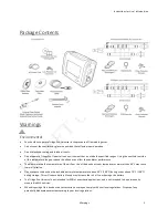
Страница 5: ...ntilator performance The blower warms the temperature of the airflow Use of the device at room temperatures warmer than 40 C may cause thermal irritation Do not expose the device or detachable battery to temperatures above 60 C 140 F during use or above 70 C 158 F during storage This will reduce battery life and may increase the risk of fire or damage the battery The Trilogy Evo Universal is not i...

Страница 6: ...values The caregiver or health care professional is responsible for verifying any changes to the device prescription or other settings before applying changes The caregiver or health care professional is responsible for ensuring settings are correct and compatible with the patient Using the wrong prescription for a patient may result in improper therapy lack of appropriate safety monitoring or ris...

Страница 7: ...esistance of breathing system filters Monitor the breathing system frequently for increased resistance and blockage Gas added by the use of a pneumatic nebulizer can adversely affect ventilator accuracy When using a passive circuit an exhalation port is required At low expiratory pressures the flow through the exhalation port may be inadequate to clear all exhaled gas from the tubing some rebreath...

Страница 8: ...al sounds if the device or detachable battery is dropped if water is spilled into the enclosure or if the enclosure is cracked or broken discontinue use and contact Philips Respironics To avoid electrical shock always unplug the power cord from the wall outlet before cleaning the ventilator Periodically inspect electrical cords cables and the detachable battery pack for damage or signs of wear Dis...

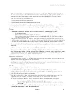
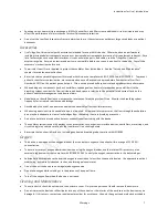
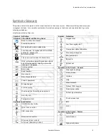
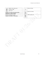
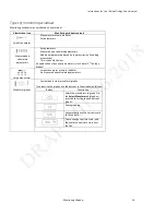
Страница 9: ...finger sized objects and protected against dripping water when tilted up to 15 degrees Catalog number Batch code Serial number Manufacturer Date of manufacture Class II equipment BF applied part LI ion recycling Waste electrical electronic equipment Humidity limit Temperature limit Symbols on the Device On Off Standby button Alarm Silence button USB connection Nurse call connection DC power direct...

Страница 10: ... priority alarm System message Alarm reset Symbols on the Screen Monitoring Views See chapter 2 About Trilogy Evo Symbols on the Screen Power See the Power Management chapter Symbols on the Screen Connectivity Bluetooth enabled Bluetooth connected USB is exporting data ...

Страница 11: ...tact Philips Respironics If you need help setting up using or maintaining Trilogy Evo Universal or if this device does not perform as expected contact Philips Respironics Call Philips Respironics Customer Service at 1 724 387 4000 1 800 345 6443 toll free 49 8152 93060 international ...

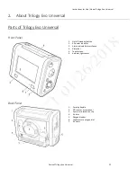
Страница 12: ...s of Trilogy Evo Universal Front Panel 1 On off standby button 2 AC power indicator 3 Alarm indicator alarm silence 4 Alarm bar 5 Touch screen 6 Ambient light sensor Back Panel 1 Carrying handle 2 FiO2 sensor access panel 3 Power cord retention clip 4 Air inlet 5 Oxygen blender 6 High pressure oxygen inlet 7 Air vents ...

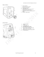
Страница 13: ...alve line connection for ActivePAP and Active Flow circuits 5 Dual limb active exhalation valve connection from patient 6 Flow sensor cable connector Utility Panel 1 AC power connector 2 Air vents 3 Low flow oxygen inlet 4 Detachable battery access door 5 Micro USB Port for device service 6 Accessory USB Port USB external storage device communication cables 7 Remote alarm or nurse call connector R...

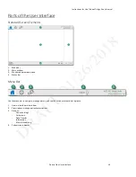
Страница 14: ...Menu bar 2 Main window 3 Monitored parameters pane 4 Status bar Menu Bar Use the menu bar to navigate manage alarms and see the active prescription at a glance 1 Home view the main window 2 Prescriptions manage patient prescriptions 3 Options Device Settings Calibration Data Transfer Information Alarm Event Log 4 Patient type indicator ...

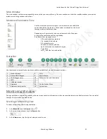
Страница 15: ... rate MinVent minute ventilation SpO2 saturation of peripheral oxygen Pulse Rate etCO2 end tidal carbon dioxide Status Bar Use the status bar to monitor device status and the availability of manual therapeutic actions 1 Manual breath 8 Wi Fi 2 Deliver 100 Oxygen 9 Alarm silence 3 100 Oxygen timer 10 Power sources and their status 4 CMD 11 5 USB data transfer 12 6 Bluetooth 13 Device Actions Menu 7...

Страница 16: ...uding accessories This is the default view An explanation of dynamic parameters is in chapter 3 Therapy Modes Large manometer Large manometer pressure indicator Six measured and calculated parameters Waveform graphs Customizable scalar waveform graphs To customize the graphs use the buttons in the window as follows Button Description Select the waveforms to graph On the Select Waveforms dialog box...

Страница 17: ...rak is a more sensitive version of Auto Trak Flow trigger initiates a breath when the patient s inspiratory effort creates a flow equal to or greater than the flow trigger sensitivity setting A lower number is more sensitive As inspiratory flow begins to decrease the device cycles to expiration when the patient flow is less than the percentage of peak flow based on the flow cycle sensitivity setti...

Страница 18: ...ing pressure modes are available for patients who require a tidal volume less than 35ml A C PC PSV S T SIMV PC Therapy Mode Comparison Table For all modes the breath type varies based on time of patient inspiration The breath type is always ventilator initiated and mandatory when the Trigger Type is set to Off Mode Breath Types Trigger Source Inspiration Cycle Exhalation Control Modes A C PC Assis...

Страница 19: ...e of breaths per minute Inspiratory Time Length of the inspiratory phase Trigger Type Auto Trak passive circuits only Sensitive Auto Trak passive circuits only Flow Trigger Passive Active PAP Active Flow or Dual Limb circuits Off Flow Trigger Sensitivity This control is available when the trigger type is Flow Trigger The flow trigger initiates when the patient s inspiratory effort creates a flow e...

Страница 20: ...Breath Rate Minimum rate of mandatory breaths per minute Flow Pattern Sets the shape of the waveform as a ramp or square Trigger Type Auto Trak Sensitive Auto Trak passive circuits only Flow Trigger Passive Active PAP Active Flow or Dual Limb circuits Off Flow Trigger Sensitivity This control is available when the trigger type is Flow Trigger The flow trigger initiates when the patient s inspirato...

Страница 21: ...rcuits only Flow Trigger Passive Active PAP Active Flow or Dual Limb circuits Flow Trigger Sensitivity This control is available when the trigger type is Flow Trigger The flow trigger initiates when the patient s inspiratory effort creates a flow equal to or greater than the flow trigger sensitivity setting Flow Cycle Sensitivity This control is available when the trigger type is Flow Trigger As f...

Страница 22: ...ting Name Description Pressure Support Target pressure that the device delivers during the inspiratory phase of a spontaneous breath PEEP Positive end expiratory pressure Rise Time Time required for the ventilator to change from the expiratory pressure setting to the inspiratory pressure setting when the breath is triggered Trigger Type Auto Trak Sensitive Auto Trak passive circuits only Flow Trig...

Страница 23: ...essure setting to the inspiratory pressure setting when the breath is triggered Breath Rate Minimum rate of breaths per minute If the patient doesn t trigger a breath within this time the ventilator triggers the breath Inspiratory Time For a mandatory breath length of the inspiratory phase Trigger Type Auto Trak Sensitive Auto Trak passive circuits only Flow Trigger Passive Active PAP Active Flow ...

Страница 24: ...livers during the inspiratory phase of a spontaneous breath PEEP Positive end expiratory pressure Positive pressure maintained in the patient circuit during exhalation must be less than or equal to the pressure setting Inspiratory Time For a mandatory breath length of the inspiratory phase Rise Time Time required for the ventilator to change from the expiratory pressure setting to the inspiratory ...

Страница 25: ...en the patient s inspiratory effort creates a flow equal to or greater than the flow trigger sensitivity setting Flow Cycle Sensitivity This control is available when the trigger type is Flow Trigger As flow begins to decrease during inspiration if the patient flow is less than the flow cycle set point the device cycles to expiration SETTABLE ALARMS Circuit disconnect High tidal volume Low tidal v...

Страница 26: ... A C VC CPAP PSV S T SIMV PC SIMV VC Insp Time Min Max Enable DESCRIPTION Set the minimum and maximum inspiratory time for pressure support breath types This feature changes inspiration time from a constant to a variable value so you can select a range for the inspiration time The range allows the patient to have a chance to cycle When the maximum time has passed with no patient initiated breath t...

Страница 27: ...en flush Tap 100 O2 in the status bar and then tap Stop APPLICABLE THERAPY MODES All Manual Breath DESCRIPTION Delivers a breath based on the current therapy mode settings To deliver a manual breath Tap the Manual Breath button in the status bar and then tap Start APPLICABLE THERAPY MODES A C PC A C VC PSV S T SIMV PC SIMV VC Therapy Control Settings Therapy control settings can be interdependent ...

Страница 28: ...conds 0 1 second increments IPAP Adult patient type 3 60 cmH2O 1 cmH2O increments Pediatric patient type 3 45 cmH2O 1 cmH2O increments Infant patient type 3 35 cmH2O 1 cmH2O increments Max Pressure 6 60 cmH2O 1 cmH2O increments PEEP Adult patient type Active circuit 0 35 cmH2O Passive circuit 3 25 cmH2O Increments 1 cmH2O Pediatric patient type Active circuit 0 25 cmH2O Passive circuit 3 25 cmH2O ...

Страница 29: ...he lung and chest wall Trilogy Evo calculates Dyn R using the following formula 𝐷𝐷𝐷𝐷𝐷𝐷 𝑅𝑅 𝑃𝑃𝑃𝑃𝑃𝑃 𝑃𝑃𝑃𝑃𝑃𝑃𝑃𝑃𝑒𝑒 𝑄𝑄𝑝𝑝 𝑡𝑡 𝐸𝐸𝐸𝐸𝐸𝐸 𝑄𝑄𝑝𝑝 𝑡𝑡 𝐸𝐸𝐸𝐸𝐸𝐸 𝑉𝑉𝑡𝑡 𝜏𝜏 Where PIP is the peak inspiratory pressure pressure at the end of inhalation 𝑃𝑃𝑃𝑃𝑃𝑃𝑃𝑃𝑒𝑒is the extrinsic pressure pressure applied by the ventilator at the end of the breath 𝑉𝑉𝑡𝑡 is the tidal volume 𝑄𝑄𝑝𝑝 𝑡𝑡 𝐸𝐸𝐸𝐸𝐸𝐸 is the patient flow at the end of the exh...

Страница 30: ...𝑃𝑃𝑃𝑃𝑃𝑃𝑃 𝑃𝑃𝑃𝑃𝑃𝑃𝑃𝑃𝑒𝑒 𝑃𝑃𝑃𝑃𝑃𝑃𝑃𝑃𝑖𝑖 𝑃𝑃𝑃𝑃𝑃𝑃𝑃𝑃𝑖𝑖 𝐷𝐷𝐷𝐷𝐷𝐷𝐷𝐷 𝑄𝑄𝑝𝑝 𝐸𝐸𝐸𝐸𝐸𝐸 this value is the intrinsic PEEP or AutoPEEP AutoPEEP Intrinsic PEEP 𝑃𝑃𝑃𝑃𝑃𝑃𝑃𝑃𝑖𝑖 is the resistive pressure at the end of exhalation EOE that occurs when a new breath is initiated before the previous breath is completed In the Measured and Calculated Parameters window this value is AutoPEEP AutoPEEP can be used as a guide to detect the pr...

Страница 31: ...ditioners Ensure the USB and detachable battery panel doors remain closed when not in use If the device has been stored outside the normal operating temperature stated in Technical Specifications ensure the device reaches operating temperature before connecting power See the EMC Information chapter for guidance on possible electromagnetic interference Connecting AC Power Use the AC cord provided t...

Страница 32: ...the filter as you press it into the filter cover as shown Position it securely behind the top and bottom restraints Particulate Filter To install a particulate filter 1 2 3 4 1 Twist the filter cover counterclockwise and pull out to remove it 2 Place the filter over the bayonet mount 3 Twist clockwise a quarter of a turn 4 Replace the filter cover and turn clockwise to secure ...

Страница 33: ...tient gas outlet port Filters not approved by Respironics may degrade system performance Note A leak device is mandatory during invasive ventilation or when using a circuit with a non vented mask After you connect the circuit you may calibrate the circuit See chapter 7 Device Options Calibration For low tidal volumes see the Therapy Modes chapter section titled Low Tidal Volume Therapy Passive Sin...

Страница 34: ...essure Port 2 3 Connect the active exhalation valve pressure line to the active exhalation valve line connection 3 Active Flow Circuits 1 Bacteria filter 2 Proximal pressure port 3 Active exhalation valve line connection 4 Flow sensor cable connector 5 Tubing 1 Connect the bacteria filter 1 on the circuit to the Inspiratory Port 2 Connect the proximal pressure line to the Proximal Pressure Port 2 ...

Страница 35: ... Connector 4 6 Attach the flow sensor to the Y shaped connector on the circuit 6 Low Tidal Volume Ventilation When using volumes between 35 and 50 ml use the infant pediatric external flow sensor with either the active flow or dual limb circuits See the operating instruction sheets included with those accessories Adding Oxygen High Pressure Oxygen To ensure accurate oxygen administration and to mo...

Страница 36: ... Low Oxygen Input Pressure High Oxygen Input Pressure Starting Trilogy Evo Universal To start Trilogy Evo Universal 1 Visually inspect Trilogy Evo Universal and all accessories cords and tubes attached to the device 2 Verify that circuit connections are secure 3 Press the On Off Standby button 4 Listen for a minimum of three beeps as Trilogy Evo Universal performs system start up checks The beeps ...

Страница 37: ...e Infant Pediatric Adult 3 Select the Patient Sex 4 For infant patients in the Weight section use the slider or the plus and minus buttons to select the patient s weight For pediatric or adult patients in the Height section select the patient s height Note this information is used to establish default therapy and alarm settings including tidal volume and alarms based on tidal volume 5 In the title...

Страница 38: ...r use the plus and minus buttons to change the parameter value 7 Tap the Alarm tab to view and edit the associated alarm settings For more information about alarms including details about each alarm see chapter 6 Alarms 8 Change the alarm parameters in the lower pane and then click Accept at the top of the window 9 Continue editing prescription and alarm parameters To work with advanced options ta...

Страница 39: ...rescription for example a daytime and nighttime prescription you can use the prescription list to change the active prescription To select a prescription that uses a circuit type that is different from the current prescription 1 Press the On Off Standby button on the front panel On the confirmation window tap Standby 2 Attach the circuit type that corresponds to the prescription 3 On the menu bar ...

Страница 40: ...stem message becomes active the screen saver is stopped and the automatic screen lock is disabled For more information see the Alarms chapter Delivering a Manual Breath To deliver a manual breath tap the Manual Breath icon in the Status Bar Delivering 100 Oxygen To deliver 100 oxygen for two minutes tap the 100 O2 icon in the Status Bar To stop delivery tap the icon again and then tap Stop ...

Страница 41: ...e this indicator see chapter 7 Device Options The Alarm Silence button on the device flashes red or yellow or glows steady yellow depending on the alarm level An audible alarm sounds Trilogy Evo Universal uses three alarm levels High Priority Requires an immediate response Medium Priority Requires a prompt response Low Priority Requires awareness Trilogy Evo Universal also shows system messages to...

Страница 42: ...ent alarm appears at the top of the list An alarm counter shows the number of active alarms Setting and Changing Alarms Warning A hazard can exist if different alarms are used for the same or similar equipment in any single area Ensure all alarms are appropriate for the patient before use You can change alarm settings when creating a new prescription or when editing an existing prescription To cha...

Страница 43: ...tilator at all times during an Alarm Silence period Allowing alarms to continue without intervention may result in harm to the patient When an alarm occurs 1 Ensure the patient has adequate ventilation and oxygen If required provide an alternate method of ventilation 2 Tap the Alarm List to view all alarms and messages If you see the help icon you can tap it for more information 3 Press the Alarm ...

Страница 44: ...9 Medium priority System Alarms 49 Circuit Leakage 49 Rebreathing Detected 50 Volume Under Delivery 50 Loss of CO2 Signal 51 Loss of SpO2 Signal 51 CO2 Sensor Adapter Zero Required 51 Check Change CO2 Airway Adapter 51 CO2 Sensor Failure 51 Low Expiratory Pressure 52 Low Inspiratory Pressure 52 Alarm See page Low Oxygen Input Pressure 52 High Oxygen Input Pressure 53 Medium priority Patient Alarms...

Страница 45: ...w sensor The ventilator detects that the exhalation port is missing What to do Check the circuit for kinked or pinched tubing Check the bacteria filter or HME for a blockage or occlusion Ensure that the exhalation port is not occluded or missing Check the external flow sensor for a blockage or occlusion Requirements Passive dual limb active PAP or active flow circuit Device performance during acti...

Страница 46: ...re connected properly and are not damaged Clean if needed Replace if necessary Requirements Active flow or dual limb circuit Device performance during active alarm The alarm remains active until the flow sensor is replaced or reconnected If the alarm occurs when delivering therapy the device will continue to operate If the alarm occurs when the device is in standby you cannot start therapy EXTERNA...

Страница 47: ... limb circuit Device performance during active alarm The alarm is automatically resolved and the device continues to operate CHECK ACTIVE EXHALATION PRESSURE CONTROL LINE Priority High Why it occurs The active exhalation pressure control line is not connected becomes disconnected or contains water droplets that affect the active exhalation valve line pressure reading What to do Inspect the line Em...

Страница 48: ...hy it occurs The patient is not properly connected to the ventilator breathing circuit or there is a large leak What to do Ensure the circuit is properly connected to both the patient and the ventilator and that a large unintentional leak does not exist Device performance during active alarm The alarm is automatically resolved when the circuit is reconnected or the excessive leak is fixed Device w...

Страница 49: ...ority on the third occurrence and then to a high priority alarm if the condition continues Occurrences must be consecutive What to do Check the patient status Check the ventilator for the following potential causes for this alarm o Kinked pinched or blocked tubing o Blocked leak device or blocked exhalation device o Secretions in the HME Device performance during active alarm Inspiration is cycled...

Страница 50: ... sum of concentration for the alarm reporting results in a shorter alarm delay when there are higher concentrations of FiCO2 The concentration estimate is based on nominal volumetric capnography curves measured flow in the inhalation limb and patient tidal volume Any three breaths without rebreathing resets the sum of percentages to zero This figure shows the assumed shape of the capnograph for a ...

Страница 51: ...d the oximeter was previously reporting valid data for 3 continuous seconds Device performance during active alarm The alarm is automatically resolved when the SpO2 probe is properly attached to the ventilator and to the patient and the oximeter reports data for more than 10 seconds Device will continue to operate CO2 SENSOR ADAPTER ZERO REQUIRED Priority Medium Why it occurs The CO2 sensor reques...

Страница 52: ...or for o Kinked pinched or blocked tubing o Circuit leak or disconnect Device performance during active alarm The alarm is automatically resolved when the delivered pressure comes within 5 cmH2O of the target patient pressure during the inspiratory phase Device will continue to operate LOW OXYGEN INPUT PRESSURE Priority Medium Why it occurs The pressure at the O2 inlet is too low to support the Fi...

Страница 53: ...he use of a nebulizer may increase tidal volumes beyond the alarm setting Device performance during active alarm The alarm is automatically resolved when a breath occurs in which the exhaled tidal volume does not reach the High Vte alarm setting Device will continue to operate Alarm Settings 10 to 2000 ml in increments of 5 ml LOW TIDAL VOLUME Priority Medium Why it occurs Passive active flow or d...

Страница 54: ...ium Why it occurs The respiratory rate is greater than the High Respiratory Rate alarm setting When the trigger type is Off then the spontaneous respiratory rate will not trigger the alarm What to do Check the patient for pain or anxiety Check the ventilator for auto triggering Note A patient in pain or in an anxious state may breathe at a higher rate Device performance during active alarm The ala...

Страница 55: ...rm Settings 90 to 100 in increments of 1 LOW ETCO2 Priority Medium Why it occurs The measured EtCO2 is less than or equal to the Low EtCO2 alarm setting for 10 seconds while the device is delivering therapy What to do Check the patient If there is a tracheal tube verify it is properly inserted Verify that leak is not excessive High leak will reduce the measured EtCO2 Review the ventilation paramet...

Страница 56: ...ments FiO2 sensor 100 O2 must not be active This alarm is disabled when 100 O2 is active Device performance during active alarm The alarm is automatically resolved when the measured FiO2 falls below the high FiO2 alarm setting in active therapy for 10 consecutive seconds Device will continue to operate Alarm Settings 27 to 100 in increments of 1 Low priority System Alarms STUCK KEY Priority Medium...

Страница 57: ...an alternate power source If no alternate power source is available immediately place the patient on an alternate source of ventilation Priority Medium priority when the last available battery is the detachable or internal battery and can provide at least 20 minutes of therapy and no more than 45 minutes of therapy Medium priority when the last available battery is the external DC source and can p...

Страница 58: ...switched to the internal battery You start therapy on internal battery power What to do Confirm the remaining battery capacity This is the last available power source Prepare an alternative power source such as AC power or an external battery Device performance during active alarm Device will continue to operate REPLACE DETACHABLE BATTERY Priority Low Why it occurs The detachable battery has faile...

Страница 59: ...he detachable battery due to temperature Detachable Battery Not Discharging Temperature The system is unable to charge the detachable battery due to temperature Start On Battery Trilogy Evo Universal is turned on and AC power is not detected Reconnect AC power Power is restored after losing all power and AC power is not detected Reconnect AC power Circuit Mismatch ActivePAP passive or dual limb ac...

Страница 60: ...to the system Testing Circuit Disconnection Alarms For ventilator dependent patients do not rely on any single alarm to detect when a circuit is disconnected One or more of the following alarms may indicate a disconnected circuit Circuit Disconnected Low Tidal Volume Low Minute Ventilation Low Respiratory Rate Low Peak Inspiratory Pressure alarms user settable for volume modes Leakage alarm Active...

Страница 61: ...e AEV control line from the ventilator 3 Confirm that the Circuit Leakage and or Check Active Exhalation Valve Line alarm activates 4 Reconnect the AEV control line and confirm that the alarm automatically resets Testing the Low FiO2 Alarm The Low FiO2 alarm requires an FiO2 sensor to be connected and the FiO2 sensor setting to be turned on To test the Low FiO2 alarm 1 Ensure that the patient is c...

Страница 62: ...et the High Tidal Volume alarm limit below the measured tidal volume value 5 Confirm that the High Tidal Volume alarm activates 6 Restore the alarm limit 7 Set the Low Tidal Volume alarm limit above the measured tidal volume value 8 Confirm the Low Tidal Volume alarm activates 9 Restore the alarm limit 10 Set the High Minute Ventilation alarm limit below the measured minute ventilation value 11 Co...

Страница 63: ...6 Restore the alarm limit SPO2 1 Set the High SpO2 alarm limit below the measured SpO2 value 2 Confirm that the High SpO2 alarm activates 3 Restore the alarm limit 4 Set the Low SpO2 alarm limit above the measured SpO2 value 5 Confirm the Low SpO2 alarm activates 6 Restore the alarm limit Alarm and Event Log The Alarm and Event Log is a record of all events related to the device and to therapy The...

Страница 64: ...s so only alarms appear in the list Tap again to view all event types 3 Alarm and event list Event Type Icon High Priority Alarm Medium Priority Alarm Low Priority Alarm Info Type Alarm Event Power or battery Physical button press Calibration event Change to therapy setting alarm setting or device option Data transfers 4 Ascending Descending button Sort the list by date and time 5 Page up and down...

Страница 65: ...tem alarm loudness Screen Brightness Set screen brightness Light Bar Turn the light bar on or off Automatic Touchscreen Lock Automatically locks the screen after five minutes of inactivity The screen automatically unlocks during an alarm Screen Saver Select the type of screen saver that you want to use Date and Format Set the system date and format Time and Format Set the system time and select 12...

Страница 66: ...default settings Information about the circuit calibration is recorded in the Event Log For more information about the Event Log see Alarm and Event Log in the Alarms chapter CALIBRATING A CIRCUIT Requirements The patient s demographics and prescription are entered into the system The patient interface is not attached to the circuit To calibrate a circuit 1 In the menu bar tap the Options icon In ...

Страница 67: ...button at the top of the window Passes tap OK O2 Sensor Calibration Prerequisites Ensure the patient circuit is connected Remove the patient interface from the circuit Remove any passive exhalation device Connect high pressure O2 Ensure that low flow O2 is not connected To calibrate the O2 sensor 1 In the menu bar tap the Options icon 2 In the Options window tap Calibration and Setup 3 In the Cali...

Страница 68: ...ons icon 3 In the Options window tap Calibration and Setup 4 In the Calibration Setup window tap CO2 Sensor Adapter Zero 5 Review the prerequisites and then tap Start 6 The system performs the test The results appear in the test progress pane If the test Fails Review the failure reasons If you want to try again tap Retest otherwise tap the Quit Passes tap OK Data Transfer Use data transfer functio...

Страница 69: ...torage device connected through Bluetooth Data is identified by the device serial number Data type Data stored Changes to the ventilator alarms prescriptions accessories and oxygen 6 months 30 second averages of each therapy parameter related to the therapy provided to the patient Waveform data including pressure flow volume and total leak 31 days Patient monitors CO2 monitor data Oximeter data Fi...

Страница 70: ...and photography credits tap the item you want to view Page 1 DME Representative Name DME Contact Phone DME Contact Email DME Company Model Number Serial Number Software Version Number Hardware Version Number Page 2 Internal Battery State of Health Detachable Battery State of Health Internal Battery Serial Number Detachable Battery Serial Number Operational Hours Total Blower Hours Operational Hour...

Страница 71: ...as Dawn Ultra Dishwashing Liquid per gallon of water 1 Turn Trilogy Evo Universal off and disconnect it from the power source 2 Detach all accessories and connectors 3 Use a lint free cloth dampened not dripping with a liquid dishwashing detergent solution to clean the exterior of the enclosure 4 Use a soft bristle brush in the areas around the screen buttons and any other areas where soil may be ...

Страница 72: ...ged contact Philips Respironics Customer Service 7 Replace the battery Open the detachable battery access door Slide the battery into the bay until you hear a click Rinsing the Air Inlet Foam Filter The air inlet foam filter is the gray foam located on the back panel It protects Trilogy Evo Universal from dirt and dust Only use Philips Respironics supplied filters Ventilation can continue while yo...

Страница 73: ...gm according to your local regulations on discarding biohazardous waste 4 Submerge the valve parts in warm water with a liquid dishwashing detergent solution 5 Agitate the parts to ensure all internal and external surfaces are saturated with the solution 6 Use a lint free cloth or cotton swab to remove all visible soil 7 Use a soft bristle brush to clean any small areas such as crevices or small o...

Страница 74: ...agm as shown in the illustration Ensure you have positioned the diaphragm correctly 9 Reassemble the valve and replace it as shown in Figures 4 and 5 in the previous section Sterilizing the External Active Exhalation Valve You can sterilize the external active exhalation valve using a hydrogen peroxide gas plasma sterilizer such as Sterrad Requirements Replacement silicon diaphragm To sterilize th...

Страница 75: ...essories for damage or signs of wear Discontinue use and replace if damaged When using oxygen to maintain accuracy calibrate the oxygen sensor daily See O2 Sensor Calibration in the Device Options chapter Monthly Replace the particulate filter when in use For invasive ventilation dispose of the air inlet foam filter Every six months Ensure the internal battery has been charged at least once in the...

Страница 76: ...to the default prescription settings reset the patient operational hours to zero and clear all existing patient data including the following event and alarm logs circuit calibration and historical data Additionally tapping New Patient deletes all Bluetooth settings If you used an external storage device that contains patient information such as a USB flash drive ensure you delete that data by refo...

Страница 77: ...void puncturing or damaging sensor membrane s Accidental release measures The oxygen sensors contain a strong basic solution encapsulated in a plastic housing Under normal operating conditions the solution electrolyte is never exposed In case of a leak please observe the following instructions Personal precautions protective equipment and emergency procedures Use personal protective equipment Avoi...

Страница 78: ...en 90 Response Time 512 seconds Linearity 3 full scale error maximum Drift 1 volume O2 per month in air Accuracy 2 5 FiO2 2 5 of actual FiO2 Expected Lifetime 1 000 000 02 hours Temperature Compensation NTC Operational Temperature Range 10 TO 40 C Storage Temperature Range 20 TO 50 C Humidity Range 0 TO 99 RH non condensing Ambient Pressure Range 700 1250mBAR Interference Per EN ISO 80601 2 55 Inf...

Страница 79: ...e white connector straight out Do not use the wires to pull the connector 4 Place the FiO2 driver on the sensor and twist counterclockwise to remove the sensor from the device 5 Because this sensor contains lead and a corrosive solution contact a licensed professional waste disposal service to dispose of this material To install a new FiO2 sensor 1 Place the sensor in the FiO2 socket 2 Place the F...

Страница 80: ...ree disposable pulse oximeter sensors are included in the package adult pediatric and infant Instructions for Use To use the oximeter sensors follow the instructions provided with the sensors To connect the oximeter to Trilogy Evo Universal plug the USB connector into the USB port on the Patient Panel Filters Air inlet foam filter The air inlet foam filter protects Trilogy Evo Universal from dirt ...

Страница 81: ... ventilator requires a patient circuit and filter s that meet the following requirements Compliance up to 4 ml cmH2O Inspiratory Expiratory Resistance Pediatric adult circuit 20 22 mm less than 5 cmH2O at 30 l min Pediatric adult circuit 19 mm less than 5 cmH2O at 15 l min Infant pediatric circuit 14 16 mm less than 5 cmH2O at 15 l min Infant pediatric circuit 9 13 mm less than 5 cmH2O at 2 5 l mi...

Страница 82: ...en Adding Oxygen to the Device Delivered oxygen concentration varies with changes in flow in the circuit The following may have an impact on oxygen concentration Pressure settings Patient Tidal Volume Peak Inspiratory Flow I E Ratio Respiratory rate Circuit leak rate Oxygen flow rate Low Flow Oxygen Warnings When administering fixed flow supplemental oxygen the oxygen concentration may not be cons...

Страница 83: ...structions that accompany the accessory Remote Alarms If you are using a remote alarm or nurse call ensure you test the accessory before starting ventilation Ensure that you can hear the ventilator s audible alarms on the remote alarm Ensure the remote alarm signals when the remote alarm cable is disconnected To use the alarm see the alarm s instructions Use the RJ9 connection on the Utility Panel...

Страница 84: ...nu bar tap the Options icon In the Options window tap Information Battery Status Indicator To view the battery status indicator tap the battery power indicator in the Status Bar Battery status This indicator shows Battery status Estimated battery time remaining for internal and detachable batteries Estimated remaining battery power shown as a percent of total capacity for external battery AC Power...

Страница 85: ...on the Status Bar Detachable Battery Trilogy Evo Universal detachable battery pack will power the ventilator if attached when Trilogy Evo Universal is disconnected from AC or external battery power The detachable battery automatically charges when plugged into AC power Battery operating time depends on the characteristics of the battery and usage of the device The capacity of the external battery ...

Страница 86: ...he Alarms chapter If all power sources are lost while Trilogy Evo Universal is delivering therapy as soon as a power source is connected the device will begin to deliver therapy again All alarm settings are retained and restored Power Indicator Icons Internal Battery Status Capacity remaining Charging 0 capacity Charging Nearly depleted Charging Low power remaining Charging 01 20 capacity Charging...

Страница 87: ...ed not charging 0 capacity or failed External Battery Status Capacity remaining Discharging 81 100 capacity Discharging 61 80 capacity Discharging 41 60 capacity Discharging 21 40 capacity Discharging 01 20 capacity Discharging Low power remaining Discharging Nearly depleted Discharging 0 capacity ...

Страница 88: ...ger sensitivity 0 5 9 l min Flow cycle 10 90 of peak flow Flow pattern Square Ramp FiO2 21 100 when available Measured and Displayed Patient Parameters Tidal volume Vti or Vte 0 to 2000 ml with a resolution of 1 ml Minute ventilation MinVent 0 to 30 l min with a resolution of 0 1 l min Leak 0 to 200 l min with a resolution of 0 1 l min Respiratory rate RR 0 to 90 BPM with a resolution of 1 BPM Pea...

Страница 89: ...x rubber or dry natural rubber Expected service life 10 years Internal memory capacity 2Gb Mode of operation Continuous Maximum limited pressure 90 cmH2O Electrical AC input voltage 100V 240V 50 60 Hz 1 7A DC input voltage 12 24V 6 5A Internal and detachable Li ion batteries 7 5 hours nominal total run time per method in IEC 80601 2 72 each battery Charge time for detachable and internal battery f...

Страница 90: ...t pediatric circuit 14 16 mm less than 5 cmH2O at 15 l min Infant pediatric circuit 9 13 mm less than 5 cmH2O at 2 5 l min Compliance Up to 4 ml cmH2O Wireless Bluetooth Operating frequency range 2402 2480 MHz Channel bandwidth 1 MHz 2 MHz Maximum output power 12 0 dBm Modulation GFSK Pi 4 DQPSK 8DQPSK Near field communication NFC Operating frequency 13 56 MHz Receiving section bandwidth 1 4 MHz M...

Страница 91: ... for the basic safety and essential performance of respiratory gas monitors Wireless communication Bluetooth Core Specification version 4 1 ISO IEC 18092 2013 Information technology Telecommunications and information exchange between systems Near Field Communication Interface and Protocol NFCIP 1 ISO IEC 21481 Ed 2 0 Information technology Telecommunications and information exchange between system...

Страница 92: ...ce Warnings Avoid using this equipment adjacent to or stacked with other equipment because it could result in improper operation Although the other equipment may comply with EMC standard requirements interference can occur If such use is necessary observe this equipment and the other equipment to verify that both are operating normally This device is unsuitable for use in a magnetic resonance imag...

Страница 93: ...ectronic equipment RF emissions CISPR 11 Class B The device is suitable for use in all establishments including domestic establishments and those directly connected to the public low voltage power supply network Harmonic emissions IEC 61000 3 2 Electromagnetic compatibility EMC Part 3 2 Limits Limits for harmonic current emissions equipment input current smaller than or equal to 16 A per phase Cla...

Страница 94: ...pply lines 1 kV for input output lines 2 kV for supply mains 1 kV for input output lines Mains power quality should be that of a typical home or hospital environment IEC 61000 4 5 Electromagnetic compatibility EMC Part 4 5 Testing and measurement techniques Surge immunity test 1 kV line to ground 2 kV line to ground 1 kV line to line N A this Class II device does not connect to earth ground Mains ...

Страница 95: ... Test IEC 60601 Test Level Compliance Level Electromagnetic Environment Guidance Conducted RF IEC 61000 4 6 Electromagnetic compatibility EMC Part 4 6 Testing and measurement techniques Immunity to conducted disturbances induced by radio frequency fields 3 Vrms 150 kHz to 80 MHz 3 Vrms 150 kHz to 80 MHz Portable and mobile RF communications equipment should be used no closer to any part of the dev...

Страница 96: ...ories may violate your local RF exposure guidelines and should be avoided This device complies with part 15 of the FCC Rules Operation is subject to the following two conditions 1 This device may not cause harmful interference and 2 this device must accept any interference received including interference that may cause undesired operation This equipment has been tested and found to comply with the...

Страница 97: ...n the Device Settings window tap Bluetooth To enable NFC connections in the Near Field Communication window tap On To disable NFC connections in the Near Field Communication window tap Off Troubleshooting If the device s display is erratic Relocate the device to an area away from electronic equipment such as cellular phones cordless phones computers TVs electronic games or hair dryers ...

Страница 98: ...inVent The volume of gas that moves in and out of the lungs in one minute It is calculated by multiplying the tidal volume by the respiratory rate Patient Circuit Consists of the tubing filtration exhaust valves passive or active and flow sensor external to the ventilator Peak Flow Maximum flow rate in liters per minute reached during a breath Peak Inspiratory Pressure PIP Highest pressure reached...

Страница 99: ...rough which gas flows at respiratory pressures and bounded by the port through which fresh gas enters the patient connection port and the exhaust port Volume Control Ventilation in which breaths are controlled by an operator defined volume flow pattern breath rate and inspiratory time Vte Exhaled Tidal Volume Vti Inhaled Tidal Volume ...

Страница 100: ...he original purchaser for the Product CONDITIONS This warranty does not cover damage or injury whether to the Product or to personal property or persons caused by accident misuse abuse negligence failure to install in accordance with Philips Respironics installation instructions failure to operate under conditions of normal use and in accordance with the terms of the operating manual and instructi...

Отзывы: