Alignments
8.
8.
Alignments
Index of this chapter:
8.1 Options
8.2 General Alignment Conditions
8.3 Hardware Alignments
8.4 Software Alignments
8.1
Options
8.1.1
Introduction
Options are used to control the presence/absence of certain
features and hardware.
How to Change an Option
Different from other Philips TV sets, the options are not
represented as bits and bytes, but with clear text.
The option settings are a part of the Service Menu. The method
of entering the Service Menu and the structure of the Service
Menu are described in “Software Alignments” below.
8.2
General Alignment Conditions
Perform all electrical adjustments under the following
conditions:
•
AC voltage and frequency: 230 V / 50 Hz.
•
Connect the set to the mains voltage via an isolation
transformer with a low internal resistance.
•
Allow the set to warm up for approximately 20 minutes.
•
Measure the voltages and waveforms in relation to chassis
ground (with the exception of the voltages on the primary
side of the power supply). Never use the cooling fins /
plates as ground.
•
Test probe: Ri > 10 Mohm; Ci < 2.5 pF.
•
Use an isolated trimmer / screwdriver to perform the
alignments.
8.3
Hardware Alignments
There are no hardware alignments present in the sets.
8.4
Software Alignments
8.4.1
Service Menu
The Service Menu enables a large number of settings. You can
activate and deactivate options, or change parameters that
influence the quality of the displayed image. Activate the
Service Menu as follows:
•
Press the “Menu” button on the remote control: the screen
will display the Customer Menu.
•
Press “1923” on the remote control: the screen will now
display the top level of the Service Menu:
–
General Setup
–
Video Setup
–
Audio Setup
–
Scaler Setup
–
Options Setup
–
Display Setup
–
More
Every item in the service menu top level gives you access to a
sublevel, that contains several items. Navigate with the cursor
buttons on the remote control, increase a value with “>”,
decrease with “<“:
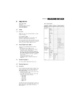
Table 8-1 Service Menu
Service Menu
Submenu
Sublevel
Parameters / Remarks
Auto Inspect
Auto Tune Menu
Input Source
SCART1
SCART2
SCART_2SV
AV
IDTV
COMPONENT
PC
DVI
HDMI1
HDMI2
TV
ADC ADJ
R Off
129 (default)
G Off
139 (default)
B Off
143 (default)
R Gain
95 (default)
G Gain
97 (default)
B Gain
105 (default)
Color
Temperature
R
50 (default) (100 steps)
G
50 (default)( 100 steps)
B
50 (default) (100 steps)
DCR EN
On/Off
(350 steps)
SRS Punch Level
20 (default) (63 steps)
Welcome Reactive On/Off
Test Pattern
On/Off
Power Mode
Every Stand-by
Every Switch-on
Latest Status
OEM Options
Panel Type
IDTV
Enable/Disable
S-Video
Enable/Disable
R/C Type
RC5302/
RC4901
Preset
Default
PH32
PH42
Version
Содержание TES2.0E
Страница 9: ...Mechanical Instructions EN 9 TES2 0E LA 4 Figure 4 3 Exploded View 32 sets H_17490_015 eps 291007 ...
Страница 10: ...Mechanical Instructions EN 10 TES2 0E LA 4 Figure 4 4 Exploded View 42 sets H_17490_016 eps 291007 ...
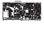
Страница 26: ...EN 26 TES2 0E LA 7 Circuit Diagrams and PWB Layouts Layout Main Board Top Side H_17490_009 eps 161007 ...

