1997 Feb 27
4
Philips Semiconductors
Product specification
IF amplifier/demodulator for FM radio receivers
TDA1597
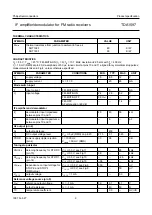
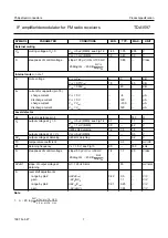
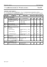
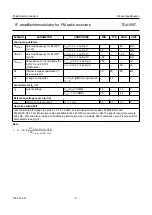
PINNING
SYMBOL
PIN
DESCRIPTION
DIP18
SO20
V
P
1
1
supply voltage (+8.5 V)
LVA
2
2
level adjustment for stop condition
ULV
3
3
unweighted level output/K2 adjustment
V
oAF
4
4
audio frequency output (MPX signal)
V
ref
5
5
reference voltage output
WLV
6
6
weighted level output
MODE
7
7
mode switch input
DDV
8
8
detune detector voltage
n.c.
−
9
not connected
DEMI1
9
10
demodulator input 1
DEMI2
10
11
demodulator input 2
n.c.
−
12
not connected
TSW
11
13
tau switch input
ST1
12
14
STOP-1, stop pulse output 1
ST0
13
15
STOP-0, stop pulse output 0
MUTE
14
16
muting voltage
GND
15
17
ground (0 V)
LFB1
16
18
IF limiter feedback 1
LFB2
17
19
IF limiter feedback 2
V
iIF
18
20
IF signal input
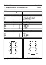
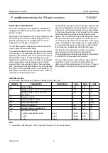
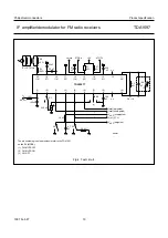
Fig.2 Pin configuration (DIP version).
handbook, halfpage
TDA1597
MED830
1
2
3
4
5
6
7
8
9
18
17
16
15
14
13
12
11
10
VP
LVA
ULV
WLV
MODE
DDV
DEMI1
VoAF
Vref
ViIF
DEMI2
TSW
ST1
ST0
MUTE
GND
LFB1
LFB2
Fig.3 Pin configuration (SO version).
handbook, halfpage
TDA1597T
MED831
1
2
3
4
5
6
7
8
9
10
20
19
18
17
16
15
14
13
12
11
VP
LVA
ULV
WLV
MODE
DDV
n.c.
DEMI1
VoAF
Vref
ViIF
n.c.
DEMI2
TSW
ST1
ST0
MUTE
GND
LFB1
LFB2


