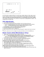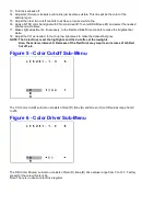
The VCO sub-menu consists of RF-AGC, H, and VIF items. RF-AGC (refers to RF AGC adjust; range of
0-127), H (refers to H VCO ADJ; range 0-7), and VIF (refers to VIF VCO adjust; range 0-63) items. Note
that when the VIF item value is being adjusted, the items AFT 0 (displays either 1/0) and AFT 1 (displays
either 1/0) are displayed permanently. AFT0 and AFT1 are not user controllable, they are used to indicate
correct alignment value settings for VIF. When the VIF sub-menu item is highlighted AFT 0 and AFT 1 are
indicated below the register value.
VCO Adjustments:
1. Tune the set to an active channel.
2. Enter the Service Default Alignment Mode (SDAM) in either of the following two ways:
a. Press the following key sequence on the remote control transmitter while the set is in Standby
mode: 0-6-2-5-9-6-Status (Do not let the sequence time-out between entries)
b. Short service pin 0239 (on the CBA) to ground and switch power-on.
3. From SDAM Menu, use the Menu Up/Down buttons to highlight VCO.
4. Use the Menu Right button to enter the VCO sub menu.
5. Use the Menu Up/Down buttons to highlight VIF.
6. Adjust the value of the VIF sub menu item so that AFT0 and AFT1 indicate 0 after the set is warmed
up.
7. After the values are set, or if no changes are required, press Menu to return to the SDAM menu.
Master Screen (VG2) White Balance Setup:
1. Apply a center cross pattern to the antenna cable input terminal.
2. Enter the Service Default Alignment Mode (SDAM) in either of the following two ways:
a.
Press the following key sequence on the remote control transmitter while the set is in
Standby mode: 0-6-2-5-9-6-Status (Do not let the sequence time-out between entries)
b. Short service pin 0239 (on the CBA) to ground and switch power-on.
3. Use the Menu Down button on the remote transmitter to highlight DR (Color Drivers).
4. Use the Menu Right button on the remote transmitter to enter the DR sub menu.
5. Record the DR values cuttently stored in each of the registers.
NOTE: Drive values range from 0-127. Factory preset for the colore driversis 63.
6. Set Red and Blue Drive Controls to mid-range (63). Green Drive is fixed at mid-range.
7. Press the Menu button to re4turn to the SDAM menu.
8. Use the Menu Up/Down on the buttons remote transmitter to highlight CO (Color Cutoff).
9. Use the Menu Left/Right buttons on the remote transmitter to set the Cutoff controls to 200.
10. Record the CO values currently stored in each of the registers.
NOTE: Cut off values range from 0-255. Factory preset values for the Cut off register is 200.
11 Press Menu to return to the main SDAM menu and power off to save.
12. With the OFF, set VG2 to minimum by rotating VG2 counterclockwise (located on the lower part of the
flyback transformer).
Содержание PR1906C121
Страница 3: ...MAIN CABINET EXPLODED VIEW Page 1 of 1 ...
Страница 5: ......
Страница 6: ......
Страница 7: ......
Страница 8: ......
Страница 9: ......
Страница 10: ......
Страница 11: ......
Страница 12: ......
Страница 13: ......
Страница 21: ...Display Feature Chart ...
Страница 22: ...Display RC1112501 Remote ...
Страница 23: ...Display RC1112901 Remote ...
Страница 24: ...Display RC282901 Remote ...
Страница 25: ...Display Jack Panel Information Chart ...
Страница 26: ......
Страница 27: ......
Страница 41: ...Fig 9a Fig 9b Fig 9c Fig 10a Fig 10b Fig 10c Figures 11 12 Yoke Tilt ...
Страница 42: ...Figure 11 Figure 12 ...
Страница 43: ...Display Figure 1 SDAM Flow Chart ...
Страница 45: ......

