Other error codes are:
•
Video Chip start-up failure
The last five errors, stored in the NVM, are shown in the service menu. This is called the error buffer.
An error code will be added to the buffer if it differs from the last error detected.
If errors occur simultaneously, and the codes for these errors differ from the errors currently on screen,
the display will be updated to reflect this change.
The error that is found last is displayed on the left. The error code to the right should be used to solve a
multiple error fault. If an intermittent fault occurs refer to the stored error code.
Example:
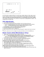
Suppose the display shows: 7 5 2 0 0
In this case, the last error detected was a Stereo I2C error.
A seven (7) appears at the 1st position (on the left), and pushes the previous error(s) detected one space
to the right.
The following error codes have been defined:
0 = No error
1 = Master Protect (Master Protect, Monitors Beam Current/Xray(6732), 8v LOT(6730), 25v
LOT(6731), vertical(6755), tuner 5v (6733), these diodes will pull pin 26 of micro 7600 low and
shut off TV.
A one (1) will be stored after the fault is cleared.)
2 = I2C error while communicating with a processor
3 = General I2C error (*)
4 = Internal RAM error micro controller
5 = I2C error EEPROM error
6 = I2C error PLL tuner
7 = Stereo I2C error
Note:
I2C =(SCL/SDA)
(*)
General I2C error means: no I2C device is responding to the particular I2C bus.
Possible causes:
SCL Short circuit to GND, SDA Short Circuit to GND, SCL Short Circuit to SDA, SDA Open Circuit
(at uP pin), SCL Open Circuit (at uP pin)
Cause and Effect
In case a failure identified by an error code automatically results in other error codes (cause and effect),
only the error code of the MAIN failure will be displayed. Example: In case of a failure of the I2C bus
(CAUSE), the error code for a „general I2C failure“ will be displayed. The error codes for the single
devices (EFFECT) won’t be displayed.
NVM replacement or Defective NVM
After replacing a NVM (or with a defective/no NVM) default settings will be used that enable the set to start
up and that allow access to the Service „SDAM“ Mode.
Service unfriendly modes
In the service modes, a number of modes/features are ignored since they interfere with diagnosing or
repairing a set. These are „service unfriendly modes.“
Содержание PR1906C121
Страница 3: ...MAIN CABINET EXPLODED VIEW Page 1 of 1 ...
Страница 5: ......
Страница 6: ......
Страница 7: ......
Страница 8: ......
Страница 9: ......
Страница 10: ......
Страница 11: ......
Страница 12: ......
Страница 13: ......
Страница 21: ...Display Feature Chart ...
Страница 22: ...Display RC1112501 Remote ...
Страница 23: ...Display RC1112901 Remote ...
Страница 24: ...Display RC282901 Remote ...
Страница 25: ...Display Jack Panel Information Chart ...
Страница 26: ......
Страница 27: ......
Страница 41: ...Fig 9a Fig 9b Fig 9c Fig 10a Fig 10b Fig 10c Figures 11 12 Yoke Tilt ...
Страница 42: ...Figure 11 Figure 12 ...
Страница 43: ...Display Figure 1 SDAM Flow Chart ...
Страница 45: ......


