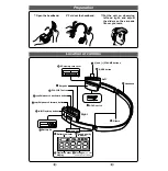
4.0 MECHANICAL INSTRUCTION
1. Remove 8pcs of screws on the side of bottom cabinet.
2. up-plug all the wire connecter from main board,
The wire connectors are for: DVD loader, battery board
and TFT driver board, and speaker.
3. up-plug the FFC from DVD driver, then you can take out
the DVD Driver.
Remove all the screws on the main board, then take the
main board from bottom cabinet.
4.
Remove the flex cable on the bottom side.
5. Remove all the screws on the buttery board, then take
out the buttery with buttery board.
Содержание PET702
Страница 7: ...3 0 INSTRUCTION FOR USE ...
Страница 15: ...5 0 TROUBLESHOOTING SYMPTOM NO SOUND FROM HEADPHONE ...
Страница 18: ...6 0 BLOCK DIAGRAM ...
Страница 24: ...7 0 Electrical Diagram Charge board ...
Страница 26: ...8 0 Component Layout Diagram TFT Charge board Top View ...
Страница 27: ...8 0 Component Layout Diagram TFT Charge board Bottom View ...
Страница 28: ...8 0 Component Layout Diagram Key Board Top View ...
Страница 29: ...8 0 Component Layout Diagram Key Board Bottom View ...