3-2
3-2
VOL -
Button pressed?
N
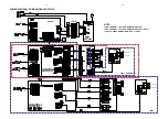
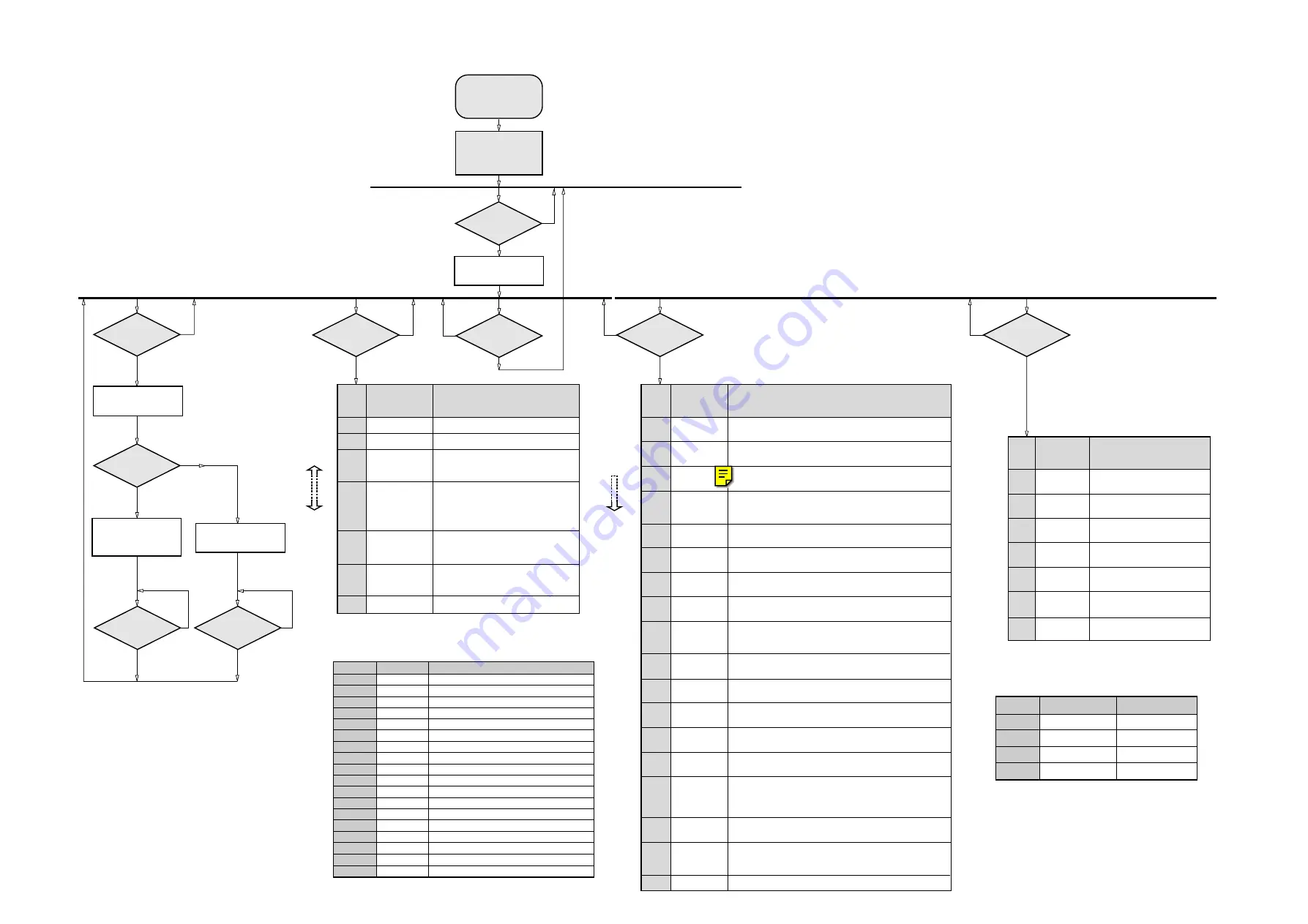
DVD DEALER TEST
(without User interaction)
STEP
1
2
3
4
5
6
ACTION
Check the correctness of the
checksum in the flash.
Check the correctness of ECHO
feature
Check the correctness of the I
2
C
bus to the NVRAM
Check writing to the NVRAM
Check writing to the SDRAM
Shows result of all tests
Returns PASS or FAIL
Disconnect mains cord to exit
the Service Test Program.
DISPLAY
CHKSUM
FLASH
S2B
ECHO
IIC
NVRAM
NVRAM
WRITE
SDRAM
WRITE
ALL TEST
’####’
DVD Dealer Test is used to check the flash RAM,
the SDRAM, the DRAM, the NVRAM and the I
2
C
communication.
Y
Table 4
Error code
0601
1101
1102
1103
1104
1201
1202
1203
1204
1301
1302
1303
1304
1601
5401
5402
5403
5403
Nucleus no.
6
11
11
11
11
12
12
12
12
13
13
13
13
16
54
54
54
54
Error description
Calculated checksum of FLASH is not correct
I
2
C bus busy before start
NVRAM access time-out
No NVRAM acknowledge
NVRAM reply time-out
I
2
C bus busy
Error sending I
2
C command to Slave
Slave controller not responding
Slave response is not correct
Parity error receiving data from Basic Engine
Parity error sending data to Basic Engine
No communication with Basic Engine
Communication time-out with Basic Engine
The SDRAM is faulty
I
2
C bus busy
Error sending I
2
C command to Scart Switch IC
Scart Switch IC not responding
Scart Switch IC response is not correct
Nucleus Error Codes
Table 3
Faulty Module Codes
Basic Engine Part
OK
OK
Faulty
Faulty
STi + Peripherals
OK
Faulty
OK
Faulty
Error code
00
01
10
11
VOL +
Button pressed?
Y
N
DVD PLAYER TEST
(with User interaction)
STEP
1
2
3
4
5
6
7
8
9
10
11
12
13
14
15
16
17
ACTION
Test picture is available on all video output. Press
B
II if test is ok,
otherwise press PROGRAM.
Noise is available on all channels. Press
B
II if test is ok,
otherwise press PROGRAM.
Internally generated pinknoise and color bar is output to all channels
& video output. Press
B
II if test is ok, otherwise press PROGRAM.
Internally generated pinknoise is output to all channels & test picture
(external signal) is send to video output. Press
B
II if test is ok,
otherwise press PROGRAM.
Sine sound output is available on all channels. Press
9
to stop the
sound output. Press
B
II if test is ok, otherwise press PROGRAM.
The color set-up function will be tested by use of internally generated
color bar. Press
B
II if test is ok, otherwise press PROGRAM.
The color set-up function will be tested by use of internally generated
color bar. Press
B
II if test is ok, otherwise press PROGRAM.
Returns the SW-version of the basic engine.
Tray 1 can be open or close with the
B
II and PROGRAM buttons
repectively. Insert a CD onto Tray 1 and close before proceding
to next test.
The Sledge can be move in and out with the
B
II and PROGRAM
buttons respectively.
Dismotor starts to turn. Press
B
II if the motor turns and PROGRAM
button if the motor does not turn.
The DVD tries to focus. Press
B
II if focus is successful and
PROGRAM button if focus is not successful.
Radial test is started. Press
B
II if test is successful and PROGRAM
button if test is not successful.
The laser spot jumps to another position. Press
B
II to jump to the
next position or press PROGRAM to jump to previous position.
Reads out the info from the error log. Up to 16 errors (8 hex digits)
can be stored in a buffer. Press
B
II to view next error or press
PROGRAM to view previous error. If there is no error the display
will shows: "LO-00000000"
Shows all error bits (2-digit number). Press
B
II to select next error
bits or press PROGRAM to select previous error bits.
Runs the dealer test infinitely. The information returned from the
module will be displayed. aa = faulty module codes (see table 3);
bbb = number of loops and cccc = Nucleus error codes (see table 4).
Disconnect mains cord to exit Service Test
DISPLAY
BAR
PICTURE
PINK
NOISE
SCART
LOOP DVD
SCART
LOOP EXT
SINE
SOUND
COLOR
HIGH
COLOR
LOW
ENG
xx.yy.zz.
TRAY
SLEDGE
MOTOR
FOCUS
RADIAL
GROOVES
LO -
wwxxyyzz
ERROR
BITS xx
’aa-bbb’
’cccc’
Go to next
step
by pressing
T
DVD Player Test allows to start several DVD specific tests.
The user has to confirm by pressing
B
II
or PROGRAM button
before going to the next step.
Environment required to run the test:
- an external video source & television connected
- loudspeakers connected
DIM
Button pressed?
Y
N
DVD VERSION
MATRIX INFO
STEP
1
2
3
4
5
6
REMARKS
Slash version number
Region code setting (Number 1 - 6)
Menu language table:
US/AP - USA / Asia Pacific language
US/EU - USA / Europe language
Audio / Subtitle language table:
1 = USA
2 = Europe
3 = AP
4 = Others
Multichannel decoding available ?
Smart picture available ?
Press
9
to exit
DISPLAY
SLASH ’###’
REGION ’#’
MULANG ’US/AP’
or
MULANG ’US/EU’
ASLANG ’#’
MULTI-CH ’YES’
or
MULTI-CH ’NO’
SMARTPIC ’YES’
or
SMARTPIC ’NO’
Choose step
by pressing
S
T
DVD Version Matrix Info is used to read the version matrix information
that are stored/defined in the DVD module software.
Y
N
Y
N
MUTE
Button pressed?
Are Software
Versions Received?
DVD I
2
C
COMMUNICATION
TEST
Send request for
DVD Software Version
via I
2
C ports
Display shows
"xx/yyy"
"zz.zz.zz"
Display shows
"FAIL"
Y
N
9
Button pressed?
Y
N
DVD I
2
C Communication Test is used to test the I
2
C communication
port between the DVD module and the microprocessor of the set.
where: xx
is the 5DTC software version
yyy
is the Backend (DVD) application software
version
zz.zz.zz
is the Basic Engine (Servo) software version
9
Button pressed?
N
Y
DISC
Button pressed?
DVD SERVICE
TEST
Y
N
9
Button pressed?
Display shows
"DVD SERVICE"
Note:
1. Remote Control must be in DVD source before start of any DVD Service Test.
2. All buttons on this "DVD SERVICE" test refers to the buttons on the Remote control.
3. Awaits for the mechanism to initialized before performing DVD test.
DVD SVC MENU
To start service test program
hold DISC1 & STANDBY-ON
buttons depressed while
plugging in the mains cord*
Display shows the
ROM version
"S-Vyy"
(Main menu)
S refers to Service Mode
V refers to Version
yy refers to Software version number of the uProcessor
(counting up from 01 to 99)
SERVICE TEST PROGRAM II
MAIN MENU
5DTC MX.. Range Service Test Program dd wk0302
* Hold till the Display is shown
Содержание MX5800SA
Страница 60: ...8239 210 93436 3139 113 3494pt6 dd wk0334 PART B 8 9 8 9 MAINS ECO STBY BOARD CHIP LAYOUT PART B ...
Страница 62: ...8 9a 8 9a MAINS ECO STBY BOARD CHIP LAYOUT PART B For pcb layout 34948 3139 113 3494 pt8 dd wk0350 PART B ...
Страница 68: ...8239 210 93416 3139 113 3494pt6 dd wk0334 PART B 8 13 8 13 SUPPLY BOARD CHIP LAYOUT PART B ...
Страница 70: ...8 13a SUPPLY BOARD CHIP LAYOUT PART B For pcb layout 34948 3139 113 3494 pt8 dd wk0350 PART B 8 13a ...
Страница 76: ...3104 213 3525p5 dd wk0334 PART B 8 19 8 19 AMPLIFIER BOARD BOTTOM VIEW PART B ...
Страница 78: ...3104 213 3525p5 dd wk0334 PART D 8 21 8 21 AMPLIFIER BOARD TOP VIEW PART D ...
Страница 91: ...9 10 9 10 BOTTOM VIEW PART C PART C ...
Страница 92: ...9 11 9 11 BOTTOM VIEW PART D PART D 3139 113 3500 pt6 dd wk334 ...
Страница 95: ...9 14 9 14 BOTTOM VIEW PART G PART G ...
Страница 96: ...9 15 9 15 BOTTOM VIEW PART H PART H 3139 113 3500 pt6 dd wk334 ...
Страница 104: ...10 5 10 5 Exploded view 5DTC mechanic for orientation only ...
Страница 111: ...BOTTOM VIEW COMPONENT LAYOUT For pcb layout 35037 11 4a 11 4a 3139 113 3503 pt 7 dd wk414 ...
Страница 112: ...TOP VIEW PART A 11 5 11 5 PART A ...
Страница 113: ...TOP VIEW PART B 11 6 11 6 PART B ...
Страница 115: ...TOP VIEW PART B For pcb layout 35037 11 6a 11 6a 3139 113 3503 pt 7 dd wk414 PART B ...
Страница 126: ...12 1 12 1 EXPLODED VIEW MAIN UNIT MX5800SA exploded view 3139 119 35170 dd wk318 ...


