background image

1-7


INFORMATION ABOUT LEAD-FREE SOLDERING 


Philips CE is producing lead-free sets from 1.1.2005 onwards.  

IDENTIFICATION: 


Regardless of special logo (not always indicated) one must treat all sets from  1 Jan 2005 onwards, according next rules: 

Example S/N: 

 
Bottom line of typeplate gives a 14-digit S/N. Digit 5&6 is the year, digit 7&8 is the week number, 
so in this case 2005 wk12 
 
So from 0501 onwards = from 1 Jan 2005 onwards


Important note: In fact also products of year 2004 must be treated in this way as long as 
you avoid mixing solder-alloys (leaded/ lead-free). So best to always use SAC305 and the 
higher temperatures belong to this. 

 
Due to lead-free technology some rules have to be respected by the workshop during a repair: 
 

• 

Use only lead-free solder alloy Philips SAC305 with order code 0622 149 00106. If lead-free solder-paste is required, please contact 
the manufacturer of your solder-equipment. In general use of solder-paste within workshops should be avoided because paste is not 
easy to store and to handle. 


• 

Use only adequate solder tools applicable for lead-free solder alloy. The solder tool must be able  

To reach at least a solder-temperature of 40


To stabilize the adjusted temperature at the solder-tip  

To exchange solder-tips for different applications. 

• 

Adjust your solder tool so that a temperature around


− 

 is reached and stabilized at the solder joint. Heating-time of the 

solder-joint should not exceed ~ 4 sec. Avoid temperatures above 400     otherwise wear-out of tips will rise drastically and flux-fluid 
will be destroyed. To avoid wear-out of tips switch off un-used equipment, or reduce heat. 

• 

Mix of lead-free solder alloy / parts with leaded solder alloy / parts is possible but PHILIPS recommends strongly to avoid mixed 
solder alloy types (leaded and lead-free).  
If one cannot avoid or does not know whether product is lead-free, clean carefully the solder-joint from old solder alloy and re-solder 
with new solder alloy (SAC305). 

• 

Use only original spare-parts listed in the Service-Manuals. Not listed standard-material (commodities) has to be purchased at 
external companies. 

• 

Special information for BGA-ICs: 
- always use the 12nc-recognizable soldering temperature profile of the specific BGA (for de-soldering always use the lead-free 
temperature profile, in case of doubt)  
- lead free BGA-ICs will be delivered in so-called 

'

dry-packaging

'

 (sealed pack including a silica gel pack) to protect the IC against 

moisture. After opening, dependent of MSL-level seen on indicator-label in the bag, the BGA-IC possibly still has to be baked dry. 
(MSL=Moisture Sensitivity Level). This will be communicated via AYS-website. 
Do not re-use BGAs at all. 


• 

For sets produced before 1.1.2005 (except products of 2004), containing leaded solder-alloy and components, all needed spare-parts 
will be available till the end of the service-period. For repair of such sets nothing changes. 


• 

On our website 

www.atyourservice.ce.Philips.com

 you find more information to:  


BGA-de-/soldering (+ baking instructions) 

Heating-profiles of BGAs and other ICs used in Philips-sets 

You will find this and more technical information within the "magazine", chapter "workshop news". 

 
For additional questions please contact your local repair-helpdesk. 
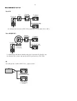
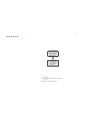
 

SERVICE INSTRUCTION 

1.  Unplug the AC Power cord and connect a wire 
     between the two pins of the AC Power plug.
2.  Set the AC Power switch to the "on" position (keep the
     AC Power cord unplugged!).
3.  Measure the resistance value between the pins of the 
     AC Power plug and the metal shielding of the tuner or 
     the aerial connection on the set. The reading should be 
     larger than 4.5 Mohm (For U.S. it should be between 
     4.2 Mohm and 12 Mohm).
4.  Switch "off" the set, and remove the wire between the 
     two pins of the AC Power plug.

Safety regulations require that after a repair, the set must be returned in its original condition. Pay in particular attention to
the following points:

·

     Route the wire trees correctly and fix them with the

      mounted cable clamps.

·

     Check the insulation of the AC Power lead for external

      damage.

·

     Check the strain relief of the AC Power cord for proper 

      function.

·

     Check the electrical DC resistance between the AC Power

      Plug and the secondary side (only for sets which have a AC
      Power isolated power supply):

    Check the cabinet for defects, to avoid touching of any 

      inner parts by the customer.
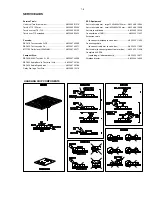
Содержание MCM240

Страница 1: ...e positions 2 Service Test Programs 3 1 Set Block diagram 4 1 Set Wiring diagram 5 1 Power Board 6 Key Board 7 Main Board 8 Set Mechanical Exploded view parts list 9 Copyright 2005 Philips Consumer Electronics B V Eindhoven The Netherlands All rights reserved No part of this publication may be reproduced stored in a retrieval system or transmitted in any form or by any means electronic mechanical ...

Страница 2: ... x News x x Dolby Pro Logic DPL Incredible Surround Karaoke Features Voltage Selector x ECO Power Standby LCD Display Off x x ECO6 Tuner Board Systems Non Cenelec x x ECO6 Tuner Board Systems Cenelec x x USB PC LINK VERSION VARIATIONS Type Versions MC240 Features Board in used SPEAKERBOARD POWERBOARD KEY BOARD MAIN BOARD OP CL BO ARD HEADPHONE BOARD VOL BOARD ANTENNA BOARD x x 21 ...

Страница 3: ... Aerial input Frame aerial 18 1µH Sensitivity at 26dB S N 4 0mV M 3 25mV M Selectivity at 300kHz bandwidth 20dB IF rejection 24dB Image rejection 20dB 28 dB Distortion at RF 50mV M 80 5 AMPLIFIER Output power L R 2 x 5W 4Ω 1kHz 10 THD Frequency response within 3dB 125Hz 16kHz Digital Sound Control DSC Jazz Rock Pop Classic Dynamic Bass Boost DBB ON OFF Input sensitivity Aux in at 1kHz 500mV at 600...

Страница 4: ...7122 707 89001 Tuner AM MW LW To avoid atmospheric interference all AM measurements have to be carried out in a Faraday s cage Use a bandpass filter or at least a high pass filter with 250Hz to eliminate hum 50Hz 100Hz RF Generator e g PM5326 Ri 50 Bandpass 250Hz 15kHz e g 7122 707 48001 LF Voltmeter e g PM2534 DUT RF Generator e g PM5326 S N and distortion meter e g Sound Technology ST1700B Use a...

Страница 5: ...822 397 30155 SBC429 Audio Signals disc 4822 397 30184 Dolby Pro logic Test Disc 4822 395 10216 ESD Equipment Anti static table mat large 1200x650x1 25mm 4822 466 10953 Anti static table mat small 600x650x1 25mm 4822 466 10958 Anti static wristband 4822 395 10223 Connector box 1MΩ 4822 320 11307 Extension cable to connect wristband to conn box 4822 320 11305 Connecting cable to connect table mat t...

Страница 6: ...ectrostatische ontladingen ESD Onzorgvuldig behandelen tijdens reparatie kan de levensduur drastisch doen verminderen Zorg ervoor dat u tijdens reparatie via een polsband met weerstand verbonden bent met hetzelfde potentiaal als de massa van het apparaat Houd componenten en hulpmiddelen ook op ditzelfde potentiaal I AVVERTIMENTO Tutti IC e parecchi semi conduttori sono sensibili alle scariche stat...

Страница 7: ...es has to be purchased at external companies Special information for BGA ICs always use the 12nc recognizable soldering temperature profile of the specific BGA for de soldering always use the lead free temperature profile in case of doubt lead free BGA ICs will be delivered in so called dry packaging sealed pack including a silica gel pack to protect the IC against moisture After opening dependent...

Страница 8: ...arked wire to Fully inser t the stripped por tion of the speaker wire into the terminal as shown Notes For optimal sound performance use the supplied speakers Do not connect more than one speaker to any one pair of speaker terminals Do not connect speakers with an impedance lower than the speakers supplied Please refer to the SPECIFICATIONS section of this manual Optional connection The optional e...

Страница 9: ...n for CD MP3 CD skips to the beginning of a current previous subsequent track 8 DBB Dynamic Bass Boost enhances the bass 9 BAND selects a waveband 0 PROGRAM for CD MP3 CD programmes tracks and reviews the programme for TUNER programmes tuner stations SOURCE selects the respective sound source for CD TUNER AUX Notes for remote control First select the source you wish to control by pressing one of t...

Страница 10: ... Netherlands CAUTION Use of controls or adjustments or performance of procedures other than herein may result in hazardous radiation exposure or other unsafe operation VAROITUS Muiden kuin tässä esitettyjen toimintojen säädön tai asetusten muutto saattaa altistaa vaaralliselle säteilylle tai muille vaarallisille toiminnoille Troubleshooting WARNING Under no circumstances should you try to repair t...

Страница 11: ...Motor Module 4 Loosen 4 screws I see Figure 3 to remove the Key_C Board 5 Loosen 2 screws J see Figure 3 to remove the Display Board Figure 6 Figure 4 Figure 3 Dismantling of the Front Boards and CD Door 6 Loosen 4 screws K see Figure 3 to remove the Key_B Board 7 Loosen 8 screws L see Figure 3 to remove the Key_A Board 8 Loosen 8 screws M see Figure 3 to remove the Door Eject Lever Bracket Right ...

Страница 12: ... depressed then STOP button depressed in standby mode Display shows the ROM version VX XX OTP MCM240 XX XX 2005 V refers to Version X XX refers to Software version number of the uProcessor eg V1 7E XX XX 200X refers to Date eg 25 5 2005 SERVICE TEST PROGRAM ...

Страница 13: ...4 1 4 1 SET BLOCK DIAGRAM ...

Страница 14: ...5 1 5 1 SET WIRING DIAGRAM ...

Страница 15: ...ted Circuit Board drawings are published for orientation only In case of defects please replace the entire board The board can be ordered with codenumber 9940 000 02866 for 21 21M 37 9940 000 02867 for 22 25 6 1 6 1 Printed Circuit Board Side A POWER BOARD Printed Circuit Board Side A ...

Страница 16: ...6 2 6 2 CIRCUIT DIAGRAM ...

Страница 17: ...ation only In case of defects please replace the entire board The board can be ordered with codenumber 9940 000 02868 for 21 21M 37 9940 000 02869 for 22 25 7 1 7 1 KEY BOARD LAYOUT DIAGRAM OPEN CLOSE BOARD TOP SIDE LAYOUT DIAGRAM OPEN CLOSE BOARD BOTTOM SIDE LAYOUT DIAGRAM VOLUME BOARD TOP SIDE LAYOUT DIAGRAM VOLUME BOARD BOTTOM SIDE ...

Страница 18: ...LAYOUT DIAGRAM KEY BOARD TOP SIDE LAYOUT DIAGRAM KEY BOARD BOTTOM SIDE 7 2 7 2 ...

Страница 19: ...7 3 7 3 CIRCUIT DIAGRAM ...

Страница 20: ... Amp Part 8 9 Circuit Diagram Tuner Part 8 10 Layout Diagrams 8 11 BLOCK DIAGRAM 2 CHANNEL AUDIO AMPLIFIER TFA9842J 60 kΩ 60 kΩ STANDBY MUTE ON SHORT CIRCUIT AND TEMPERATURE PROTECTION VREF 0 5VCC VCC VCC 9 4 IN1 IN2 OUT1 OUT2 SVR CIV MODE 1 3 7 8 2 6 5 GND TFA9842J BLOCK DIAGRAM AM FM IF FM STEREO DETECTOR TA2099N TFA9842J IN2 OUT2 CIV IN1 GND SVR MODE OUT1 VCC 2 1 3 4 5 6 7 8 9 PIN CONFIGURATION...

Страница 21: ... 3 4 5 6 7 8 9 10 11 12 13 14 15 31 30 29 28 27 26 25 24 23 22 21 20 19 18 17 Micro controller interface Audio out circuit Digital output 16 k RAM Address circuit LPF Sub code decoder CLV servo ROM RAM Digital equalizer automatic adjustment circuit Servo control PWM A D D A Data slicer VCO PLL TMAX Clock generator 1 bit DAC Synchronous guarantee EFM decoder BLOCK DIAGRAM CD Player Processor TC94A1...

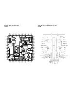
Страница 22: ...BLOCK DIAGRAM MICROCONTROLLER UNIT TMP87PP23F 8 3 8 3 ...

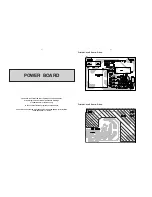
Страница 23: ...LAYOUT DIAGRAM MAIN BOARD TOP SIDE 8 4 8 4 ...

Страница 24: ...8 5 8 5 LAYOUT DIAGRAM MAIN BOARD BOTTOM SIDE ...

Страница 25: ...CIRCUIT DIAGRAM MAIN BOARD MCU PART 8 6 8 6 ...

Страница 26: ...CIRCUIT DIAGRAM MAIN BOARD CD PART 8 7 8 7 ...

Страница 27: ...CIRCUIT DIAGRAM MAIN BOARD MP3 PART 8 8 8 8 ...

Страница 28: ...CIRCUIT DIAGRAM MAIN BOARD AMP PART 8 9 8 9 ...

Страница 29: ...CIRCUIT DIAGRAM MAIN BOARD TUNER PART 8 10 8 10 ...

Страница 30: ...NE BOARD BOTTOM SIDE LAYOUT DIAGRAM MOTOR BOARD LAYOUT DIAGRAM SWITCH BOARD LAYOUT DIAGRAM ANTENNA BOARD LAYOUT DIAGRAM SPEAKER BOARD TOP SIDE LAYOUT DIAGRAM LED BOARD TOP SIDE LAYOUT DIAGRAM LED BOARD BOTTOM SIDE LAYOUT DIAGRAM SPEAKER BOARD BOTTOM SIDE 8 11 8 11 ...

Страница 31: ... SELF TAPPING SCREW TA KH 2 6x8mm 12 17 HARDEN SCREW BTTB 2x8 MC 19 15 HARDEN SCREW BTTB 2 6x8mm MC 28 2 SELF TAPPING SCREW TB KH 3x8 HD5mm 38 1 MACHINE SCREW MS BH 3x4 mm 41 14 HARDEN SCREW BTTB 3x12 AB 43 2 SELF TAPPING SCREW TA WH 3x12mm 48 1 SCREW TA BWH 3x10mm HD 12mm 51 2 NUT ID 3 OD 5 5 T 2 3mm 59 2 MACHINE SCREW MS KH 3x8mm HD 5mm 61 4 SELF TAPPING SCREW TA WH 3x10mm H D 10mm 63 9 HARDEN S...

Страница 32: ...000002835 TRANSISTORS MMBT3906LT1 FS303 994000002865 SUBMINI FUSE 200mA 250V 22 Q215 994000002834 TRANSISTORS MMBT3904LT1 IC1 994000002842 IC MM1469PH Q301 994000001193 TRANSISTORS KSB772YS IC101 994000002844 IC TA2157FN Q302 994000002834 TRANSISTORS MMBT3904LT1 IC102 994000002849 IC TC94A14FAG Q402 994000002834 TRANSISTORS MMBT3904LT1 IC103 994000002853 IC XC61FC3012MR Q403 994000002834 TRANSISTO...

Страница 33: ...TRANSFORMER AC230V 22 25 VD201 994000002836 VARICAP DIODE 1SV 149 VD202 994000002836 VARICAP DIODE 1SV 149 994000002866 POWER BD ASS Y 21 21M 37 994000002867 POWER BD ASS Y 22 25 994000002868 KEY BD ASS Y 21 21M 30 37 994000002869 KEY BD ASS Y 22 25 Note Only these parts mentioned in the list are normal service parts 9 3 9 3 ...

Отзывы: