background image

8 - 2

8 - 2

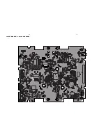
LAYOUT DIAGRAM -  POWER & AMP BOARD

Содержание MCM239

Страница 1: ... CD playability 1 1 1 4 Specifications 2 Connection Controls 3 Disassembly Instructions 4 Block Wiring diagrams 5 C MUSIC USB BOARD 6 KEY USB JACK BOARD 7 POWER AMP JACK BOARD 8 EXPLODE DIAGRAM 9 SERVICE PARTLIST 10 FACTORY PARTLIST 11 ...

Страница 2: ...ICE AIDS GB WARNING All ICs and many other semi conductors are susceptible to electrostatic discharges ESD Careless handling during repair can reduce life drastically When repairing make sure that you are connected with the same potential as the mass of the set via a wrist wrap with resistance Keep components and tools also at this potential ESD CLASS 1 LASER PRODUCT GB Safety regulations require ...

Страница 3: ...replace CD Drive Laser current ok N Y check Laser current CD Drive offsets ok N Y check CD Drive offsets clean the lens check playability return set Customer complaint CD related problem return set return set replace CD Drive return set replace CD Drive return set replace Signal Processor return set fast lens cleaning 1 2 3 4 5 6 7 For flap loaders access to CD drive possible cleaning method 4 is ...

Страница 4: ...ted to contact the workshop directly The lens cleaning method 3 should be mentioned in the addendum sheet The final wording in national language as well as the printing is under responsibility of the Regional Service Organizations 3 FAST LENS CLEANING dry brush Use lens cleaning CD SBC AC300 9082 100 00043 Insert the lens cleaning CD press PLAY and follow the voice guide s instructions on the CD 4...

Страница 5: ... with a DC Millivoltmeter directly on the connector see drawing below Pin numbering varies from drive to drive The values from diode A D should read 0 10mV Diodes E and F are less critical If one of the offsets is higher than 10mV the CD drive has to be replaced Otherwise replace the Signal Processor Sanyo DA12T3 CD Drive A A F C B E C D E VCC B VREF F D 9 10 11 12 13 14 15 16 1800 5V_HF VrefCD10 ...

Страница 6: ...M 75 Ω wire MW Loop antenna SPEAKERS Bass reflex system Dimensions w x h x d 158 x 250x 118 mm GENERAL INFORMATION AC Power 220 240V 50 Hz Dimensions w x h x d with without the stand 211 x 250 x 160 211 x 250 x 126 mm Weight with without speakers 2 9 1 23 kg Standby power consumption 2 W Eco power standby 1 W Specifications and external appearance are subject to change without notice USB 12Mb s V1...

Страница 7: ...ntenna supplied can only be used to receive nearby stations For better reception we recommend using a cable antenna system or an outdoor antenna 1 Extend the wire antenna and fit it to FM ANTENNA as shown below Note If you are using a cable antenna system or an outdoor antenna fit the antenna plug instead of the wire antenna to FM ANTENNA 2 Move the antenna in different positions for optimal recep...

Страница 8: ...es to radio stations ÉÅ CD starts or pauses playback 6 IR sensor for the infrared remote control Helpful hints Always point the remote control towards this sensor 7 DSC Digital Sound Control selects predefined sound settings ROCK JAZZ POP CLASSIC OPTIMAL 8 STANDBY ON ECO POWER press briefly to switch the set on or off standby ECO POWER In standby or Eco Power mode press and hold to toggle between ...

Страница 9: ...ime In standby mode enters the clock setting mode press and hold for more than 2 seconds DSC Digital Sound Control selects predefined sound settings ROCK JAZZ POP CLASSIC OPTIMAL TIMER ON OFF switches the timer on off Notes for remote control First select the source you wish to control by pressing one of the source select keys on the remote control for example CD TUNER Then select the desired func...

Страница 10: ...s C Remove Amplifier board C1 Remove screws 2 pcs C2 Remove screws 2 pcs C1 C1 C2 C2 D Remove Main board D1 Remove screws MP 3x10 3 pcs D2 Remove screws MP 2x8 6 pcs E Remove Key board E1 Remove screws MP 2x8 8 pcs D2 D2 Then remove lens frame cosmetic top_right left Then remove lens frame cosmetic botom_right left E1 E1 ...

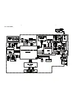
Страница 11: ...5 1 5 1 SET BLOCK DIAGRAM ...

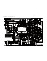
Страница 12: ...5 2 5 2 SET W IRING DIAGRAM ...

Страница 13: ...6 1 6 1 CIRCUIT DIAGRAM C music USB BOARD part1 ...

Страница 14: ...6 2 6 2 CIRCUIT DIAGRAM C music USB BOARD part2 ...

Страница 15: ...6 3 6 3 LAYOUT DIAGRAM C music USB BOARD ...

Страница 16: ...7 1 7 1 KEY USB JACK BOARD ...

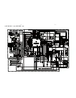
Страница 17: ...8 1 8 1 CIRCUIT DIAGRAM POWER AMP JACK BOARD ...

Страница 18: ...8 2 8 2 LAYOUT DIAGRAM POWER AMP BOARD ...

Страница 19: ...EXPLODE DIAGRAM 9 1 9 1 ...

Страница 20: ...6991 COVER PLAY BUTTON 31 9965 100 06992 COVER NAVIGATION BUTTON 32 9940 000 01664 DAMPER GEAR ASSEMBLY 33 9965 100 06993 LENS CD AMBI LIGHT GUIDE L 34 9965 100 06994 LENS CD AMBI LIGHT GUIDE R 35 9965 100 06995 SPRING FOR OPEN BUTTON 1 36 9965 100 06996 SPRING FOR OPEN BUTTON 2 37 9965 100 06997 SPRING FOR DOOR CD CDMECHA 9965 100 06482 CD MECHANISM CMS M93BGPJ FFC 9965 100 01359 FFC CABLE 10P L ...

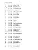
Страница 21: ... IC SAA6581T RDS PHILIPS SO16 X901 9965 100 06961 CRYSTALHC 49 U4 332MHZ 20PPM ELECTRICAL PARTS POWER BOARD D801 9965 100 06964 DIODE 1N5819 DO 41 D802 9965 100 06964 DIODE 1N5819 DO 41 JK801 9940 000 01619 SP TERMINAL MSP 134V 05 JK802 9940 000 03318 HP JACK D3 6MM JK803 9965 100 06969 DC JACK 3PIN DC 005 DIA6 3MM K101 9965 100 06970 SWITCH OPEN CLOSEDTS 031P1T2 4 L810 9965 100 06968 INDUCTOR 3A1...

Страница 22: ...AMPLIFIER TFA9842BJ U803 9965 000 41716 IC CMOS RESET BD4844G SSOP5 U804 9965 100 06967 IC AZ1117 3 3E1 VOLTAGE REG ZD803 9965 000 41721 ZENER DIODE BZX79 C10 ZD804 9965 100 06965 CH ZENER DIODE RLZ12B LL 34 ELECTRICAL PARTS KEY BOARD LED801 9965 100 06971 LED 3MM XY 030RDL10 TACTSW 9940 000 04259 SWITCH TACT TSA 06430 150 Note Only these parts mentioned in the list are normal service parts ...

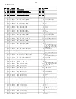
Страница 23: ...C 4 000 C419 C420 C421 C422 4 0210 1121 105041020 CH CAP CER 1UF 10V 5 0603 PC 1 000 C177 4 0215 1121 225041020 CH CAP CER 2 2UF 10V 5 0603 PC 2 000 C123 C124 4 0220 1132 105083060 CAP ELECT 1UF 50V 20 5X11 TAPING PC 8 000 C409 C410 C411 C413 C415 C416 C4 23 C424 4 0230 1132 475083060 CAP ELECT 4 7UF 50V 20 5X11 TAPING PC 2 000 C407 C418 4 0240 1132 226063060 CAP ELECT 22UF 25V 20 5X11 TAPING PC 7...

Страница 24: ...0 IC AP1117E33LA REGULATOR SOT223 PC 1 000 IC601 4 0790 1512 001117130 IC AZ1117H 3 3TRE1 REGULATOR SOT 223 PC 1 000 IC601 4 0800 1513 008861000 IC ET8861S SSOP48 LCD DRIVER PC 1 000 U201 4 0810 1606 047090000 CH INDUCTOR4 7UH 10 DCR 0 9R Q 45 CMI3216 4R7K PC 3 000 FB801 FB802 FB803 4 0820 1606 100185000 CHOCK COIL 10UH Q 30 DCR 1 85OHM 0603 PC 1 000 L202 4 0850 1614 330094000 INDUCTOR 33UH 10 0 9...

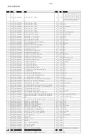
Страница 25: ...2 TAPING PC 1 000 C846 4 0140 1132 227053061 CAP ELECT 220UF 16V 20 5X11 105DEGREE TAPING PC 1 000 C808 4 0150 1132 477053220 CAP ELECT 470UF 16V 20 8X12 TAPING PC 1 000 C807 4 0160 1138 104082110 CAP MMF HMFS 0 1UF 50V 10 6 8x5 0 TAPING PC 2 000 C858 C859 4 0170 1211 047072000 RES 4 7R1W 5 PC 1 000 R801 4 0180 1211 561052000 RES 560R1 10W 5 PC 1 000 R885 4 0190 1231 393042000 RES 39K 1 8W 5 TAPIN...

Страница 26: ...21 4 0020 1221 000062020 CH RES 0 OHM1 16W 5 0603 PC 1 000 R221 4 0030 1221 152062020 CH RES 1 5K1 16W 5 0603 PC 2 000 R208 R214 4 0040 1221 182062020 CH RES 1 8K1 16W 5 0603 PC 2 000 R209 R215 4 0050 1221 222062020 CH RES 2 2K1 16W 5 0603 PC 2 000 R210 R216 4 0060 1221 332062020 CH RES 3 3K1 16W 5 0603 PC 4 000 R207 R211 R213 R217 4 0070 1221 472062020 CH RES 4 7K1 16W 5 0603 PC 2 000 R212 R218 4...

Страница 27: ...0 4 FORFRONTCABINETCONTROLPANEL 3 0070 6012 226100110 SCREW PTTN M 2 6X10 PB DIA 12 0 PC 4 000 1 FORDAMPERGEAR 2 FORPOWERPCBREARCABINET 1 FORREARCABINET 2 0040 8943 061100200 PACKING PART OF MCM238 12 SET 1 000 3 0010 7103 030300100 LABEL DON T TOUCH THE LENS PC 1 000 3 0020 7107 030600100 LABEL QC PC 1 000 3 0030 7111 061100200 LABEL TYPE PLATE 52X35MM MCM238 12 PC 1 000 3 0040 7101 061100200 LAB...

Страница 28: ...11 060600010 SMPS ADAPTOR 15V 1 2A FOR EUROPE IMPORT230 240V VDE PC 1 000 2 0060 8951 061100100 STAND PORTION OF MCM238 12 SET 1 000 3 0010 5912 061100100 AND BASE PC 1 000 3 0020 6802 061100200 STEEL FOR STAND BASE PC 1 000 3 0030 6404 061100200 RUBBER FOOT FOR STAND BASE PC 2 000 3 0040 6023 230040100 SCREW M B B3X4B TOYO A023004002 PC 4 000 4 STEELSTANDBASE 11 6 FACTORY BOM ...

Отзывы: