background image

16

PHILIPS LTC3963/51 (E) QR31809

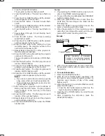
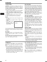
1. Press the START/STOP button.

The program number (1) flashes on/off.

2. Press the SET button.  The start hours flash on/

off.

3. Press the UP or DOWN button until the desired

number appears on the monitor.

4. Press the SET button.  The start minutes flash

on/off.

5. Press the UP or DOWN button until the desired

number appears on the monitor.

6. Press the SET button.  The stop hours flash on/

off.

7. Repeat steps 3 through 5 to set the stop hours

and minutes.

8. Press the SET button.  The timer recording

speed flashes on/off.

9. Press the UP or DOWN button until the desired

number appears on the monitor.

10. Press the SET button after setting the timer

recording speed.  The program number of the
next lower line flashes on/off.

11. Repeat steps 2 through 9 to set the program to

the other program numbers.

12. Press the SET button after setting the program

numbers (1) through (7).
The two program event locations of MON flash
on/off.

13. Press the SET button.  The first program event

location of MON flashes.

14. Press the UP or DOWN button until the desired

program number appears on the monitor.

15. Press the SET button.  The other program event

location of MON flashes on/off.

16. Press the UP or DOWN button until the desired

program number appears on the monitor.
Notes:
• If you do not need to timer record two events

a day, mark either event with an asterisk (

).

• If two asterisks are displayed, no timer record-

ing is made on that day.

17. After setting two program event locations of

MON, press the SET button.  The two program
event locations of the next day of the week
flashes on/off.

18. Press the SET button.  The first program event

location of the next day flashes.

19. Repeat steps 12 through 16 to set the program

event locations up to SUN.

20. Press the START/STOP button when the TIMER

has been set.

Notes:
1. Programming the TIMER function does not acti-

vate it.  See TIMER recording, page 21.

2. To record the time and date press the PROGRAM

button to display them.

3. When the preset START time is later than the

STOP time, the recording will be made into the
following day.

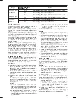
4. When the START time and STOP time are the

same, a recording will not be made.

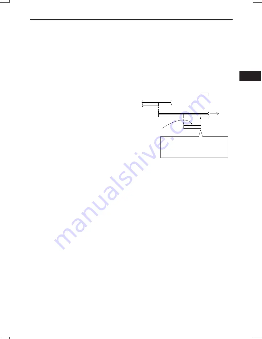
5. When the programs for timer recording overlap

each other, recording will be switched to the pro-
gram with the later recording start time.

6. When two programs have the same start time,

the program number with the earlier stop time
has priority.

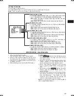
To correct information

1. Press the START/STOP button.
2. Press the UP or DOWN button repeatedly until

the item to be corrected (Program number or
program event location of day of the week)
flashes on/off.

3. When the section to be corrected flashes on/off,

press the SET button.
• Press the SET button again so that only the

digit to be corrected flashes on/off.

4. Press the UP or DOWN button to correct the set

information.

5. After completing the correction, press the

START/STOP button.

,,

,,

,,

,,,

,,,

Example

• • • • •

Record

Time

Program number 1

Program number 2

Program number 3

When recording of program 
number 3 is terminated, program 
number 2 will be recorded for its 
remaining time.

Содержание LTC 3963/51

Страница 1: ...Time lapse Video Recorder LTC 3963 51 Instructions for Use Eng D F I E NL ...

Страница 2: ... This plug will only fit into a grounding type power outlet This is a safety fea ture If you are unable to insert the plug into the outlet contact your electrician to replace your obsolete outlet Do not defeat the safety purpose of the grounding type plug 12 Power Cord Protection Power supply cords should be routed so that they are not likely to be walked on or pinched by items placed upon or agai...

Страница 3: ...h is in the ON position The power cord is the main power disconnect for all units External Power Supplies Use Only the Recommended Power Supplies Power supplies must comply with the requirements of the latest version of IEC 65 VDE 0860 Substitutions may damage the unit or cause a fire or shock hazard 220 240 V 50 Hz power cords input and out put must comply with the latest versions of IEC Publicat...

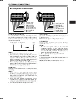
Страница 4: ...NS 2 PRECAUTIONS 4 CONTROLS AND FUNCTIONS 5 INSTALLATION 9 EXTERNAL CONNECTIONS 10 CASSETTE TAPES 12 SETUP 13 SETTING THE TIME AND DATE 14 SETTING OPTIONS ITEMS 15 SUMMER TIME FUNCTION 15 SETTING THE TIMER 15 SETTING THE VCR FUNCTIONS 17 SETTING THE BUZZER 18 SETTING THE ALARM 19 ALARM MEMORY RECALL AND RESET 20 OPERATION 21 TAPE RECORDING 21 REC CHECK 21 AUTO REC CHECK 21 ONE SHOT RECORDING 21 TI...

Страница 5: ...agnet or magnetized object near the VCR because it will adversely affect the per formance of the VCR Do not install the unit in an inclined position The unit is designed for operation in a horizontal position Operation Condensation If you pour a cold liquid into a glass water vapor in the air will condense on the surface of the glass This is the condensation of moisture Condensation on the head dr...

Страница 6: ... to decrement change or reverse to the previous lower value 11 UP BUTTON Press to increase change or advance to the next higher value 12 V POS VERTICAL POSITION BUTTON Press repeatedly to control the vertical position of the programmable display on the monitor 13 H POS HORIZONTAL POSITION BUTTON Press repeatedly to control the horizontal position of the programmable display on the monitor 14 ALARM...

Страница 7: ...ON Press to start recording 25 STOP BUTTON Press to stop the tape The STOP button must be pressed to end the RECORD and PLAY mode 26 PLAY BUTTON Press to play recorded material in the forward direc tion Pressing this during recording makes it possible to check recordings 27 REVERSE PLAY BUTTON Press to play recorded material at the 09 72 120 168 240 speed in the reverse direction during the PLAY m...

Страница 8: ...the following cases A cassette is not loaded A cassette without its safety tab is loaded The timer has not been programmed 36 LOCK INDICATOR LOCK appears when the recorder is in the security lock mode 37 VCR MODE INDICATORS appears during recording t t appears during the rewind mode s s appears during the fast forward mode t t or s s flashes during visual search s appears during the playback mode ...

Страница 9: ... monitor or another recorder 9 dBm 600 ohm unbalanced 45 AC INLET 46 RS 232C INTERFACE D SUB25 JACK Used to operate this VCR from a personal computer on control system 47 EXTERNAL INTERFACE 15 PIN JACK Connect an alarm switch door sensor etc using the 15 pin adapter provided q ALARM A IN w ALARM OUT e ONE SHOT IN r TAPE END OUT t TAPE END RESET y WARNING OUT u ALARM B IN i TIME ADJUST o CAMERA SW ...

Страница 10: ...ation use of cameras having line locked vertical sync or a gen locked master drive sync source is highly re commended The use of vertical interval switchers is also recommended Video Output Connect the monitor to the Video OUT BNC terminal on the rear panel AUDIO CONNECTIONS Note Audio recording can be performed at the 09 and 27 hour recording speeds and audio playback at the 09 and 27 speeds Audi...

Страница 11: ...nds When you have selected DURATION in the ALARM OUT menu in the ALARM display no voltage is applied after the alarm recording ends The output impedance is approx 100 ohm ONE SHOT IN One shot recording is possible when pin e is shorted to pin 5 Note Do not apply a voltage to pin e or 5 TAPE END OUT Approx 12V is applied to pin r when the tape reaches the end Notes This does not operate when you ha...

Страница 12: ...pin 3 The above resistance values have a tolerance of 2 REC CHECK IN Recording can be checked when pin 4 is shorted to pin 5 during recording mode The recorded ma terial is played back for several seconds so that you can check whether recording is made normally or not WARNING OUT When an abnormality has occurred in this VCR approx 5V is output to pin y to warn the user TIME ADJUST When two or more...

Страница 13: ...removed Notes The TAB indicator lights when a cassette without its safety tab is loaded To record again on a cassette that has its safety tab removed cover the tab hole with tape In the TIMER mode the TIMER indicator will flash on and off if the cassette is inserted without its safety tab slot covered or intact TAPE LENGTH The total recording time at each of the eight tape speeds depends on the le...

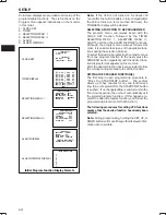
Страница 14: ... is turned on for more than 48 hours the TIME DATE display will be cleared SELECTING A FUNCTION TO BE PROGRAMMED The program menu will always begin with the CLOCK SET function followed by the TIMER SELECTION MENU 1 SELECTION MENU 2 ALARM and then the ALARM MEMORY functions Although the program menu always follows this order it is possible to skip any of the available func tions during the selectio...

Страница 15: ... the seconds will start counting and the clock will start CLOCK SET will flash on off again at this time 13 To display the time date you have set here on the monitor screen press the START STOP but ton again to cause OPTIONS to flash and then proceed with step 2 in item on OSD TYPE on page 15 14 Press the START STOP button three times Make sure that letters CLOCK SET or OPTIONS are not flashing No...

Страница 16: ...ne You can change the hour display in one hour steps without any limit by pressing the above buttons Note Summer time cannot be set unless TIME DATE is displayed SETTING THE TIMER To set the 24 Hour On Off Timer function 1 Press the START STOP button twice so that OPTIONS flashes on off 2 Press the SET button so that the OSD TYPE set ting flashes on off 3 Press the UP or DOWN button to select the ...

Страница 17: ...After setting two program event locations of MON press the SET button The two program event locations of the next day of the week flashes on off 18 Press the SET button The first program event location of the next day flashes 19 Repeat steps 12 through 16 to set the program event locations up to SUN 20 Press the START STOP button when the TIMER has been set Notes 1 Programming the TIMER function d...

Страница 18: ...ing at the 09 speed mode SEARCH SPEED 3 5 7 or 9 times the normal speed You can select the visual search speed ONE SHOT REC 2 4 6 8 FIELD You can select the number of fields to be recorded during one shot recording BAUD RATE 1200 2400 4800 9600 BAUD You can select the transmission speed with the personal computer CAMERA SW 27 ALL 09 ONLY You can select the timing with which pulses are output to sw...

Страница 19: ...ep sounding if recording is abnormal Buzzer will not sound even if recording is abnormal ALARM OUT ON or OFF To specify whether buzzer turns on or off when alarm is output ON OFF Buzzer will keep sounding if alarm is output Buzzer will not sound even if alarm is output SELECTION MENU 2 Format Description 1 Press the START STOP button The TAPE END option OFF flashes on off 2 Press the SET button re...

Страница 20: ...MANUAL 5 15 30 SEC 1 3 5 10 30 60MIN TAPE END 3 Press the SET button The record speed setting flashes on off 4 Press the UP or DOWN button until the desired setting appears on the monitor 09 240 HR 5 Press the SET button The alarm ready setting flashes on off 6 Press the UP or DOWN button to select the alarm ready function YES or NO Select YES if you want to start alarm record ing even in the norm...

Страница 21: ...eset the ALARM memory When the ALARM RESET button is pressed once if PL is flashing PL will disappear Press the button again to clear the ALARM memory When PL is not flashing press the ALARM RESET button once to clear the ALARM memory ALARM MEMORY Display Format Description LARM M M 1 A 00 A 2 3 4 5 6 7 8 9 ORY E Displays the number of alarm inputs that have occurred Counts up to 99 inputs ALARM C...

Страница 22: ...N triggers the recording of 6 fields the recording of 5 6 fields per second If the next signal is not received in approx 3 min utes the VCR will automatically record 6 fields This process will be repeated approx every 3 minutes To record in this mode follow the tape recording procedure steps 1 through 3 setting the tape speed mode at 00 You can select the number of fields to be recorded in the ONE...

Страница 23: ...rd playback resumes when the PLAY but ton is pressed Notes When the REVERSE PLAY button is pressed in the forward playback mode to set the VCR to the reverse playback mode the first several frame images may be distorted When the REVERSE PLAY button is pressed during playback at the 27 or 48 hour speed reverse play is performed automatically at the 72 hour speed The VCR will automatically enter the...

Страница 24: ... to start playback 2 Press the ALARM INDEX button 3 Press the REW or F FWD button The recorder enters VISUAL SEARCH mode 4 When the VCR finds a mark it enters normal playback mode 5 Press REW or F FWD button again to find next marked recording The recorder advances tape to the next marked position 6 Press the ALARM INDEX button again to release alarm index search Notes 1 If another alarm comes thr...

Страница 25: ...ansmitted consecutively or another command is transmitted before the VCR has ended an operation the VCR returns the SX BUSY EX code Re transmit the command 5 If there is a mistake in the received communications format the VCR returns one of the following commu nication error codes ERL Error in code length ERC Error in code format ERT Error inside the VCR when return is not possible within about 2 ...

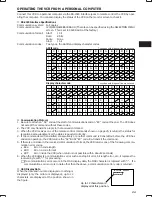
Страница 26: ...S XAL E X u are pressed Counter reset S XCO E X S XCO E X t Tape end reset S XTE E X S XTE E X Controls pin t System control microprocessor reset S XSY E X Tape speed S XSPD rE X S XSPDE X Specifies the recording playback mode OSD screen number S XSCR nE X S XSCRE X OSD horizontal display position up S XHO E X S XHO E X OSD horizontal display position S XHOR jjE X S XHORE X OSD vertical display po...

Страница 27: ...zzzE X u Tape end signal S XEND E X S XEND e gE X t Symbol Identification Type of code Details of code a Alarm yes no ASCII 1 Alarm input 0 No alarm aa Number of alarms ASCII 2 digit number 00 99 or E0 E9 b Safety tab on cassette ASCII 1 Tab 0 No tab bbb Running status ASCII Three letters STO Stop FPL Playback REC Recording STI Still RAD Reverse frame advance REW Rewind FWD Fast forward REV Revers...

Страница 28: ...SCII 2 digit number 00 59 ttt Tape status ASCII Three letters NTP No cassette END End of tape BGN Start of tape NRM Normal status u ALARM READY ASCII Y Yes N No v Power failure yes no ASCII 1 Power failure 0 No power failure vv Vertical display start position ASCII 2 digit number 02 22 w Alarm index ASCII 1 ON 0 OFF www Day of the week ASCII Three letters SUN Sunday MON Monday TUE Tuesday WED Wedn...

Страница 29: ...rol may need to be returned to center position if previously adjusted The TRACKING control is only active for the 09 or 27 mode Replace cassette Clean video heads Remove cassette and reinsert Check the LOCK indicator on the front panel If the indicator is lit press both SET and DOWN buttons simultaneously to release the security lock Check the TAB indicator is lit See Note on page 12 Be sure there...

Страница 30: ... 3 kHz 09 mode Power AC 230V 50 Hz Power Consumption 23W Cabinet Size 435 mm W x 94 mm H x 366 mm D Weight Approx 6 2 kg Design and specifications are subject to change without notice Maintenance Two periodic maintenance steps are recommended to insure the peak performance of this products 1 Periodically make a careful observation of the quality of the playback video If there are excess ive dropou...

Страница 31: ...switched on when it is unattended unless it is specifically stated that it is designed for unattended operation or has a standby mode Switch off using the switch on the equipment and make sure that your family know how to do this Special arrangements may need to be made for infirm or handicapped people DON T use equipment such as personal stereos or radios so that you are distracted from the requi...

Страница 32: ...s Communication Security Systems Inc All Rights Reserved Philips is a registered trademark of Philips Electronics North America Corporation Data subject to change without notice Printed in Japan 8960 392 45101 QR31809 ...

Страница 33: ...Time lapse Video Recorder LTC 3963 61 Instructions for Use Eng F E ...

Страница 34: ...erous voltage points or short out parts that could result in a fire or electric shock Never spill liquid of any kind on the unit 16 Servicing Do not attempt to service this unit yourself as open ing or removing covers may expose you to dangerous voltage or other hazards Refer all servicing to qualified service personnel 17 Damage Requiring Service Unplug the unit from the outlet and refer servicin...

Страница 35: ...h is in the ON position The power cord is the main power disconnect for all units External Power Supplies Use Only the Recommended Power Supplies Power supplies must comply with the requirements of the latest version of IEC 65 VDE 0860 Substitutions may damage the unit or cause a fire or shock hazard 220 240 V 50 Hz power cords input and out put must comply with the latest versions of IEC Publicat...

Страница 36: ...TIONS 2 PRECAUTIONS 4 CONTROLS AND FUNCTIONS 5 INSTALLATION 9 EXTERNAL CONNECTIONS 10 CASSETTE TAPES 12 SETUP 13 SETTING THE TIME AND DATE 14 SETTING OPTIONS ITEMS 15 SUMMER TIME FUNCTION 15 SETTING THE TIMER 15 SETTING THE VCR FUNCTIONS 17 SETTING THE BUZZER 18 SETTING THE ALARM 19 ALARM MEMORY RECALL AND RESET 20 OPERATION 21 TAPE RECORDING 21 REC CHECK 21 AUTO REC CHECK 21 ONE SHOT RECORDING 21...

Страница 37: ...agnet or magnetized object near the VCR because it will adversely affect the per formance of the VCR Do not install the unit in an inclined position The unit is designed for operation in a horizontal position Operation Condensation If you pour a cold liquid into a glass water vapor in the air will condense on the surface of the glass This is the condensation of moisture Condensation on the head dr...

Страница 38: ...ss to decrement change or reverse to the previous lower value 11 UP BUTTON Press to increase change or advance to the next higher value 12 V POS VERTICAL POSITION BUTTON Press repeatedly to control the vertical position of the programmable display on the monitor 13 H POS HORIZONTAL POSITION BUTTON Press repeatedly to control the horizontal position of the programmable display on the monitor 14 ALA...

Страница 39: ...N Press to start recording 25 STOP BUTTON Press to stop the tape The STOP button must be pressed to end the RECORD and PLAY mode 26 PLAY BUTTON Press to play recorded material in the forward direc tion Pressing this during recording makes it possible to check recordings 27 REVERSE PLAY BUTTON Press to play recorded material at the 06 72 120 168 or 240 speed in the reverse direction during the PLAY...

Страница 40: ...the following cases A cassette is not loaded A cassette without its safety tab is loaded The timer has not been programmed 36 LOCK INDICATOR LOCK appears when the recorder is in the security lock mode 37 VCR MODE INDICATORS appears during recording t t appears during the rewind mode s s appears during the fast forward mode t t or s s flashes during visual search s appears during the playback mode ...

Страница 41: ...or a monitor or another recorder 9 dBm 600 ohm unbalanced 45 RS 232C INTERFACE D SUB25 JACK Used to operate this VCR from a personal computer on control system 46 EXTERNAL INTERFACE 15 PIN JACK Connect an alarm switch door sensor etc using the 15 pin adapter provided q ALARM A IN w ALARM OUT e ONE SHOT IN r TAPE END OUT t TAPE END RESET y WARNING OUT u ALARM B IN i TIME ADJUST o CAMERA SW OUT 0 RE...

Страница 42: ...n use of cameras having line locked vertical sync or a gen locked master drive sync source is highly re commended The use of vertical interval switchers is also recommended Video Output Connect the monitor to the Video OUT BNC terminal on the rear panel AUDIO CONNECTIONS Note Audio recording can be performed at the 06 18 and 30 hour recording speeds and audio play back at the 06 A18 and A30 speeds...

Страница 43: ...nds When you have selected DURATION in the ALARM OUT menu in the ALARM display no voltage is applied after the alarm recording ends The output impedance is approx 100 ohm ONE SHOT IN One shot recording is possible when pin e is shorted to pin 5 Note Do not apply a voltage to pin e or 5 TAPE END OUT Approx 12V is applied to pin r when the tape reaches the end Notes This does not operate when you ha...

Страница 44: ...d to pin 3 The above resistance values have a tolerance of 2 REC CHECK IN Recording can be checked when pin 4 is shorted to pin 5 during recording mode The recorded ma terial is played back for several seconds so that you can check whether recording is made normally or not WARNING OUT When an abnormality has occurred in this VCR approx 5V is output to pin y to warn the user TIME ADJUST When two or...

Страница 45: ...otes The TAB indicator lights when a cassette without its safety tab is loaded To record again on a cassette that has its safety tab removed cover the tab hole with tape In the TIMER mode the TIMER indicator will flash on and off if the cassette is inserted without its safety tab slot covered or intact TAPE LENGTH The total recording time at each of the nine tape speeds depends on the length of th...

Страница 46: ...arged after the VCR is turned on for more than 48 hours the TIME DATE display will be cleared SELECTING A FUNCTION TO BE PROGRAMMED The program menu will always begin with the CLOCK SET function followed by the TIMER SELECTION MENU 1 SELECTION MENU 2 ALARM and then the ALARM MEMORY functions Although the program menu always follows this order it is possible to skip any of the available func tions ...

Страница 47: ...2 Press the START STOP button the seconds will start counting and the clock will start CLOCK SET will flash on off again at this time 13 To display the time date you have set here on the monitor screen press the START STOP but ton again to cause OPTIONS to flash and then proceed with step 2 in item on OSD TYPE on page 15 14 Press the START STOP button three times Make sure that letters CLOCK SET o...

Страница 48: ...hour display in one hour steps without any limit by pressing the above buttons Note Summer time cannot be set unless TIME DATE is displayed SETTING THE TIMER To set the 24 Hour On Off Timer function 1 Press the START STOP button twice so that OPTIONS flashes on off 2 Press the SET button so that the OSD TYPE set ting flashes on off 3 Press the UP or DOWN button to select the setting OFF FULL or HA...

Страница 49: ...sks are displayed no timer record ing is made on that day 17 After setting two program event locations of MON press the SET button The two program event locations of the next day of the week flashes on off 18 Press the SET button The first program event location of the next day flashes 19 Repeat steps 12 through 16 to set the program event locations up to SUN 20 Press the START STOP button when th...

Страница 50: ... of fields to be recorded during one shot recording BAUD RATE 1200 2400 4800 9600 BAUD You can select the transmission speed with the personal computer CAMERA SW 18 ALL 06 ONLY You can select the timing with which pulses are output to switch the camera SELECTION MENU 1 Format Description ELECT O ELD I SE E E A D P E CH S X5 M S R ON E R E C AU SH R T 6F D A 0B D 0 BAU T 96 A W R M E CA A S LL ENU ...

Страница 51: ...ep sounding if recording is abnormal Buzzer will not sound even if recording is abnormal ALARM OUT ON or OFF To specify whether buzzer turns on or off when alarm is output ON OFF Buzzer will keep sounding if alarm is output Buzzer will not sound even if alarm is output SELECTION MENU 2 Format Description 1 Press the START STOP button The TAPE END option OFF flashes on off 2 Press the SET button re...

Страница 52: ...MANUAL 5 15 30 SEC 1 3 5 10 30 60MIN TAPE END 3 Press the SET button The record speed setting flashes on off 4 Press the UP or DOWN button until the desired setting appears on the monitor 06 240 HR 5 Press the SET button The alarm ready setting flashes on off 6 Press the UP or DOWN button to select the alarm ready function YES or NO Select YES if you want to start alarm record ing even in the norm...

Страница 53: ...eset the ALARM memory When the ALARM RESET button is pressed once if PL is flashing PL will disappear Press the button again to clear the ALARM memory When PL is not flashing press the ALARM RESET button once to clear the ALARM memory ALARM MEMORY Display Format Description LARM M M 1 A 00 A 2 3 4 5 6 7 8 9 ORY E Displays the number of alarm inputs that have occurred Counts up to 99 inputs ALARM C...

Страница 54: ...s the recording for 2 4 6 or 8 fields the recording of 6 67 fields per second If the next signal is not received in approx 3 min utes the VCR will automatically record 2 4 6 or 8 fields This process will be repeated approx every 3 minutes To record in this mode follow the tape recording procedure steps 1 through 3 setting the tape speed mode at 00 You can select the number of fields to be recorded...

Страница 55: ... resumes when the PLAY but ton is pressed Notes When the REVERSE PLAY button is pressed in the forward playback mode to set the VCR to the reverse playback mode the first several frame images may be distorted When the REVERSE PLAY button is pressed during playback at the A18 A30 30 or 48 hour speed reverse play is performed automatically at the 72 hour speed The VCR will automatically enter the ST...

Страница 56: ...Y button to start playback 2 Press the ALARM INDEX button 3 Press the REW or F FWD button The recorder enters VISUAL SEARCH mode 4 When the VCR finds a mark it enters normal playback mode 5 Press REW or F FWD button again to find next marked recording The recorder advances tape to the next marked position 6 Press the ALARM INDEX button again to release alarm index search Notes 1 If another alarm c...

Страница 57: ...itted consecutively or another command is transmitted before the VCR has ended an operation the VCR returns the SX BUSY EX code Re transmit the command 5 If there is a mistake in the received communications format the VCR returns one of the following commu nication error codes ERL Error in code length ERC Error in code format ERT Error inside the VCR when return is not possible within about 2 seco...

Страница 58: ... XMLIE X u way as when its buttons Alarm reset S XAL E X S XAL E X u are pressed Counter reset S XCO E X S XCO E X t Tape end reset S XTE E X S XTE E X Controls pin t System control microprocessor reset S XSY E X Tape speed S XSPD rE X S XSPDE X Specifies the recording playback mode OSD screen number S XSCR nE X S XSCRE X OSD horizontal display position up S XHO E X S XHO E X OSD horizontal displa...

Страница 59: ... E X S XTOT xxxxx zzzzzE X u Tape end signal S XEND E X S XEND e gE X t Symbol Identification Type of code Details of code a Alarm yes no ASCII 1 Alarm input 0 No alarm aa Number of alarms ASCII 2 digit number 00 99 or E0 E9 b Safety tab on cassette ASCII 1 Tab 0 No tab bbb Running status ASCII Three letters STO Stop FPL Playback REC Recording STI Still RAD Reverse frame advance REW Rewind FWD Fas...

Страница 60: ...digit number 00 59 ttt Tape status ASCII Three letters NTP No cassette END End of tape BGN Start of tape NRM Normal status u ALARM READY ASCII Y Yes N No v Power failure yes no ASCII 1 Power failure 0 No power failure vv Vertical display start position ASCII 2 digit number 02 22 w Alarm index ASCII 1 ON 0 OFF www Day of the week ASCII Three letters SUN Sunday MON Monday TUE Tuesday WED Wednesday T...

Страница 61: ...eturned to center position if previously adjusted The TRACKING control is only active for the 06 A18 or A30 mode Replace cassette Clean video heads Remove cassette and reinsert Check the LOCK indicator on the front panel If the indicator is lit press both SET and DOWN buttons simultaneously to release the security lock Check the TAB indicator is lit See Note on page 12 Be sure there is a cassette ...

Страница 62: ...g type 3 prong AC plug Power Consumption 22W Cabinet Size 435 mm W 94 mm H 366 mm D 17 1 8 W 3 11 16 H 14 7 16 D Weight Approx 6 2 kg 13 7 lbs Design and specifications are subject to change without notice Maintenance Two periodic maintenance steps are recommended to insure the peak performance of this product 1 Periodically make a careful observation of the quality of the playback video If there ...

Страница 63: ...30 ...

Страница 64: ...ommunication Security Systems Inc All Rights Reserved Philips is a registered trademark of Philips Electronics North America Corporation Data subject to change without notice Printed in Japan 3935 890 20781 99 24 QR31808 ...

Отзывы: