


Service Modes, Error Codes, and Fault Finding
5.
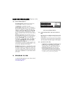
Table 5-1 Error code overview
Notes
1.
Some of the error codes reported are depending on the
option code configurations.
2.
This error means: no I
2
C device is responding to the
particular I
2
C bus. Possible causes: SCL/SDA shorted to
GND, SCL shorted to SDA, or SCL/SDA open (at uP pin).
The internal bus of the NXP (Loctop) platform should not
cause the entire system to halt as such an error can be
reported.
5.4.4
How to Clear the Error Buffer
The error code buffer is cleared in the following cases:
•
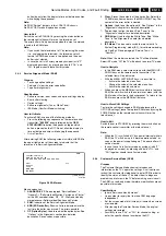
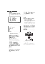
By using the CLEAR command in the SAM menu:
–
To enter SAM, press the following key sequence on the
remote control transmitter:
“062596”
directly followed
by the
OSD/STATUS/INFO/i+
button (do not allow the
display to time out between entries while keying the
sequence).
–
Make sure the menu item CLEAR is selected. Use the
MENU UP/DOWN buttons, if necessary.
–
Press the MENU RIGHT button to clear the error
buffer. Press the right button twice (1st is to select the
text “Yes“ on the right side menu and the 2nd press is
to clear the error buffer in NVM the text “CLEARED” will
appear).
•
If the contents of the error buffer have not changed for 50
hours, the error buffer resets automatically.
Note:
If you exit SAM by disconnecting the mains from the
television set, the error buffer is not reset.
5.5
The Blinking LED Procedure
5.5.1
Introduction
The software is capable of identifying different kinds of errors.
Because it is possible that more than one error can occur over
time, an error buffer is available, which is capable of storing the
last five errors that occurred. This is useful if the OSD is not
working properly.
Errors can also be displayed by the blinking LED procedure.
The method is to repeatedly let the front LED pulse with as
many pulses as the error code number, followed by a period of
1.5 seconds in which the LED is “off”. Then this sequence is
repeated.
Example (1):
error code 4 will result in four times the sequence
LED “on” for 0.25 seconds / LED “off” for 0.25 seconds. After
this sequence, the LED will be “off” for 1.5 seconds. Any RC5
command terminates the sequence. Error code LED blinking is
in red / White colour (refer to Error codes overview).
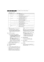
Example (2):
the content of the error buffer is
“1 2 9 6 0 0”
After entering SDM, the following occurs:
•
1 long blinks of 5 seconds to start the sequence,
•
12 short blinks followed by a pause of 1.5 seconds,
•
9 short blinks followed by a pause of 1.5 seconds,
•
6 short blinks followed by a pause of 1.5 seconds,
•
1 long blinks of 1.5 seconds to finish the sequence,
•
The sequence starts again with 12 short blinks.
5.6
Software Upgrading
In this chassis, the following SW “stacks” is used:
•
TV main SW (processor and processor NVM).
5.6.1
TV Main SW Upgrade
For instructions on how to upgrade the TV Main software, refer
to ComPair.
5.6.2
Service SSB
It should be noted that in this chassis the HDCP-key is
embedded in the main processor. Therefore there is no need
for a separate Service-SSB.
Error code Description
Item no. Remarks
1
DC Protection of speakers
7C01
1) TV in protection mode
2) Red LED blinking 1 time (Error 1)
*Error 1 logged in SAM and CSM mode
2
+12V protection error
1) TV in protection mode
2) Red LED blinking 2 times (Error 2)
*No error buffer logged in SAM and CSM mode (protect time very short)
3
I
2
C Standby uP
7303
1) TV turn on with picture, but without Sound output from speaker
2) Red LED blinking 3 times & 4 times (Error 3 & 4)
*No communication between LOCTOP and WT
*First check WT and Second check LOCTOP generical I
2
C
*Error 3 logged in SAM and CSM mode
4
General I
2
C error
7C01
1) TV turn on without Picture & Sound output from speaker
2) Red LED blinking 3 times & 4 times (Error 3 & 4)
*No communication between LOCTOP and WT
*First check WT and second check LOCTOP generical I
2
C
*No error buffer logged in SAM and CSM mode
6
I
2
C error while communicating with the NVM
7302
1) TV turn on after 3 seconds in Standby mode.
2) Power on TV set (RC) again (wait until TV turn on with blud screen displayed)
3) Input RC sequence ( menu)
4) White LED blink 6 times (Error 6)
*No error buffer logged in SAM and CSM mode
7
I
2
C error while communicating with the Tuner.
1104
1) TV turn on after 3 seconds in Standby mode.
2) Power on TV set (RC) again. TV with snow (no video) displayed.
3) Input RC sequence ( menu)
4) White LED blink 7 times (Error 7)
*Error 7 logged in SAM and CSM mode
8
I
2
C error while communicating with the IF
Demodulator.
7401
1) TV turn on after 3 seconds in Standby mode
2) Power on TV set (RC again). (wait for 45 seconds, until the system completed the power on state check)
3) Input RC sequence ( menu)
4) White LED blink 8 times (Error 8)
*Error 8 logged in SAM and CSM mode


