background image

EN 18

L03.2L AA

7.

Circuit Diagrams and PWB Layouts

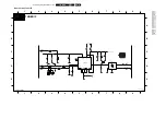
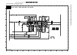
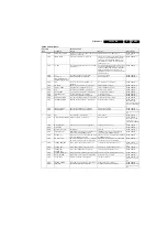
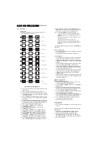
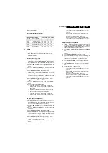
Mono Carrier: Audio - BTSC Stereo Decoder

CTRL AMP

L-R

VOLUME

LEFT

CTRL

FIL

REF

AND

TONE

RIGHT

CTRL

TONE

LEFT

CTRL

NC

NC

VOLTAGE

DET AND

DEMATRIX
+

NC

MODE

SELECT

TRANSC

INPUT

SELECT

STEREO DECODER

AUTOMATIC

RIGHT

CTRL

LOGIC

VOLUME

I2C

VOLUME AND

LEVEL CONTROL

L+R

SUPPLY

RES

4V1

4V1

0V0

4V1

1861 B5
1883 E4
2861 B4
2862 C2
2863 C3
2864 B5
2865 B5
2866 D7
2867 D7
2868 D7
2869 D8
2870 B8
2871 B7
2872 B7
2873 B7
2874 D5
2875 D5
2876 B6
2877 D5
2878 D5
2879 D4
2880 D3
2881 D7

A6

3V3

4V1

4V1

4V1

4V1

1

2

3

4

5

6

7

8

9

10

11

1

2

3

4

5

6

7

8

9

10

11

A

4V1

4V1

6V7

A4

6V6

A6

4V1

4V1

RES

0V0

4V1

RES

RES

B

C

D

E

F

G

A

B

C

D

E

F

G

4V1

4V1

4V1

4V1

2882 D6
2883 E4
2884 B4
2885 B4
2886 E2
2891 B2
3861 D6
3862 C4
3863 D3
3864 D3
3865 F4
3866 E4
3867 B5
4852 D8
4861 E8
4863 B8
4865 E8
5861 E4
5862 F9
7861 C4

4V1

1V1

4V1

0V

AUDIO - BTSC STEREO DECODER  (ECONOMIC)

0V0

RES

4V1

A7

4V1

4V1

4V1

0V0

4V

3V3

4V1

0V0

A7

A1

RES

4V1

4V1

8V1

8V2

4V1

0V0

4V1

0V0

0V0

A4

A4

470u

2883

2885

220n

100u

2875

1K2

3863

1883

1

4n7

2879

A2

A5

4u7

2876

2878

2863

1u

2874

100u

2882

4852

4861

47n

2870

100n

2886

2871

150p

VIR

24

VREF

27

100R

3865

44

OUTL

16

OUTR

18

RFR

7

SCL

40

SD

A

38

13

TC1L

TC1R

21

TC2L

14

20

TC2R

TW

30

11

VA

L

23

VA

R

VCAP

28

VCC

41

VIL

10

CPH

42

CSS

6

31

CW

DGND

37

35

FDI

FDO

33

LIL

8

LIR

26

LOL

9

25

LOR

MAD

39

1

12

17

22

34

TDA9853H

7861

A

GND

36

15

BCL

BCR

19

BPU

32

CA

V

29

CER

43

CMO

5

COMP

4

CP1

3

CP2

2

2867

3n3

10u

5861

4865

2891

100n

150p

2868

2u2

2884

3K3

3867

2873

2u2

47n

2869

10u

2877

4863

2881

CSB

1861

514K5

5862

10u

15K

3862

100R

3864

3n3

2872

2u2

2866

2864

2u2

A4

2u2

2862

A3

100K

3861

22n

2880

2u2

2865

3866

100R

SDA

SCL

+8V

Main_OutL

R1_IN

L1_IN

AM_FM_MONO

Main_OutR

220n

2861

3139 123 5802.1

E_14560_007.eps

150304

A4

0.5V / div DC

1ms / div.

A5

0.5V / div DC

1ms / div.

Содержание L03.2L AA

Страница 1: ......

Страница 2: ...Directions for Use 5 4 Mechanical Instructions 6 5 Service Modes Error Codes and Fault Finding 7 6 Block Diagrams Testpoint Overviews and Waveforms Block Diagram 11 I2C and Supply Voltage Overview 12 Testpoint Overview Mono Carrier and CRT Panel 13 7 Circuit Diagrams and PWB Layouts Diagram PWB Mono Carrier Power Supply A1 14 21 24 Mono Carrier Deflection A2 15 21 24 Mono Carrier Tuner IF A3 16 21...

Страница 3: ...r WRMS 1 x 1 3005 models 2 x 1 3205 models 1 1 3 Miscellaneous Power supply Mains voltage VAC 220 240 44 models 105 132 55 models Mains frequency Hz 50 60 Ambient conditions Temperature range C 5 to 40 Maximum humidity 90 R H 1 2 Connection Overview Note The following connector colour abbreviations are used acc to DIN IEC 757 Bk Black Bu Blue Gn Green Gy Grey Rd Red Wh White and Ye Yellow 1 2 1 Fr...

Страница 4: ... 1 3 Chassis Overview Figure 1 3 Chassis overview B1 MONO CARRIER A1 A2 A3 A4 POWER SUPPLY DEFLECTION A5 AUDIO AMP MONO SOUND PROC TUNER IF IF VIDEO PROCESSING CONTROL AND SYNC FRONT I O FRONT CONTROL HEADPHONE AUDIO BTSC STEREO DECODER CRT PANEL A6 A7 E_14560_013 eps 240304 ...

Страница 5: ...commend a maintenance inspection carried out by qualified service personnel The interval depends on the usage conditions When a customer uses the set under normal circumstances for example in a living room the recommended interval is three to five years When a customer uses the set in an environment with higher dust grease or moisture levels for example in a kitchen the recommended interval is one...

Страница 6: ...g time of the solder joint should not exceed 4 sec Avoid temperatures above 400 C otherwise wear out of tips will rise drastically and flux fluid will be destroyed To avoid wear out of tips switch off unused equipment or reduce heat Mix of lead free soldering tin parts with leaded soldering tin parts is possible but PHILIPS recommends strongly to avoid mixed regimes If not to avoid clean carefully...

Страница 7: ...nter clips outward 1 At the same time pull the panel away from the CRT 2 3 If necessary disconnect the degaussing coil by removing the cable from the red connector 1512 4 Move the panel somewhat to the left and flip it 90 degrees 3 with the components towards the CRT Figure 4 1 Service Position 4 3 Rear Cover Mounting Before you mount the rear cover perform the following checks 1 Check whether the...

Страница 8: ...ck Blue mute Hotel hospitality mode Auto switch off when no IDENT video signal is received for 15 minutes Skip blank of non favorite presets channels Auto store of personal presets Auto user menu time out Operation hours counter Software version Option settings Error buffer reading and erasing Software alignments How to enter SDAM Use one of the following methods Use a standard customer RC transmi...

Страница 9: ...s after you have switched on the Customer Service Mode The new Personal preference value is automatically stored White line around picture elements and text Decrease the SHARPNESS value when The picture improves after you have pressed the Smart Picture button on the remote control The new Personal preference value is automatically stored Snowy picture No or bad antenna signal Connect a proper ante...

Страница 10: ...omPair interface 3 Connect the AC power adapter to the supply connector marked with POWER 9V DC on the ComPair interface 4 Switch the ComPair interface OFF 5 Switch the television set OFF remove the AC power 6 Connect the ComPair interface cable between the connector on the rear side of the ComPair interface marked with I2 C and the ComPair connector on the mono carrier see figure Top view Mono Ca...

Страница 11: ... deflection Reason line transistor 7421 is defective Set is dead and makes no sound Check power supply IC 7520 Result voltage at pins 2 6 7 9 and 11 are about 180 V and pin 14 is 0 V The reason why the voltage on these pins is so high is because the output driver pin 11 has an open load That is why MOSFET 7521 is not able to switch Reason feedback resistor 3523 is defective Caution be careful meas...

Страница 12: ...R H OSC PLL 3463 3465 2490 3464 7463 7461 7465 7462 12V V DRIVE V DRIVE 3470 7466 7464 3474 3451 2455 HEADPHONE A7 L L R R L L R R V7 V8 5602 3642 3643 3605 3604 5603 5601 A3 A5 FRONT CONTROL A7 CONTROL A4 3 3V WP 3601 3602 3V3 3 3V F1 57 1621 12MHz 58 1 KEYBOARD LOCAL KEYBOARD CHANNEL VOLUME 7200 B TDA93XX VST PWM DAC ROM RAM CPU IIC BUS I O PORTS 11 7 3 2 8 6 5 54 61 56 IR 62 8 7641 M24C04 EEPRO...

Страница 13: ...7901 or 1 7902 5V FILAMENT FILAMENT 3V3A AUDIO FRONT I O A7 3V3A Vaudio 1x 1x 3x 2x VIDEO PROCESSING B1 A4 Vaudio FILA MENT 4379 3493 7493 3494 3 A1 A2 In 1 3495 5482 4491 3V3 5V 8V 1x 8VD 3V3A 6491 7494 6492 3496 3497 7496 7491 3492 3491 VTSupply A 8V 2x 1x 1x Vaudio VIDEO PROCESSING A4 TUNER IF A3 3605 7641 M24C16 EEPROM NVM 3604 3643 3642 6 5 3 2 11 WP 7 ERR 9 7200 B SET PROCESSOR PART OF VIDEO...

Страница 14: ...v V11 1V div DC 20µs div V12 1V div DC 20µs div V13 1V div DC 20µs div V14 1V div DC 20µs div V7 0 5V div DC 20µs div V8 0 5V div DC 20µs div F1 1V div AC 2ms div D4 0 5V div DC 5ms div D5 0 5V div DC 5ms div V2 D6 1V div AC 5ms div P6 2V div DC 5µs div A4 0 5V div DC 1ms div A5 0 5V div DC 1ms div P5 100V div DC 5µs div P2 97V DC P3 13V5 DC P4 17V8 DC E_14560_019 eps 180304 D1 97V DC 2 2 1 6 7 3 ...

Страница 15: ... B5 6501 B6 6502 B5 V Standy Mode 330K 6503 B6 6505 D2 6520 E2 6522 F6 6540 F8 6541 E9 6560 D8 6561 D9 6562 C9 6580 A8 7451 F10 7515 F7 7520 D2 7521 E6 7523 F1 7540 F9 7541 G8 7580 A7 9502 C4 9503 A6 9505 D2 9509 D8 5521 1501 PFC5000 5520 D 3M3 0R15 8V0 COLD 9V1 114V3 3V8 POWER SUPPLY 14RF 1N5 SS28032 02A RGP15D RGP15D 13V 19V 2523 12V4 0V0 12V0 9V1 8V8 16V5 4V7 220V AC 309V 317V A2 BYV95A RES Ite...

Страница 16: ...0N 13N 33N 100N NO A4 A4 22N 150K 3R9 3R9 1R 150K 8K2 2K2 47K JF0501 19276 4R7 4R7 NO 2473 470p 470u 2446 3447 3451 3455 3460 5441 3R3 3R3 NO 560N 15N15N 1N 2K2 33K 47K 22N NO NO 36K 47K 100K 4R7 3R9 3R9 220K 19V 13V 14RF JF0501 19255 3R3 3R3 3473 3474 2406 2408 2423 2424 2441 2452 2494 3402 3440 3441 3442 3443 3444 3445 2455 10u 16V 6445 BAS316 1n 2461 5421 PSD10 204B 1 3 5 6 RGP10D 6447 BC817 25...

Страница 17: ...9 A 5002 C5 5003 C6 5004 E6 6001 C7 1004 1 UV1336 3004 100R BZX79 C33 RES A4 A4 A4 A4 RES A4 TUNER IF T1 5001 820n 100R 3003 2001 10n 5002 EH B 1003 1 2 3 8 4 SCL 5 SDA 2 TU 7 VS 9 VTS 5003 1000 TUNER 1 AGC 3 AS 10 11 IF 12 13 14 15 6 10V 470u 2006 3005 100R 5004 100u 2002 3002 22K 6001 OFWG1984M 1001 1 2 3 22p 2003 3001 4K7 2004 22p 2005 220n 10u 2007 5V SCL SDA VIF_2 VIF_1 TUNER_AGC VTSupply_A V...

Страница 18: ...To 1300 8V3 A5 1V0 0V 2V6 3V3 3V3 0V2 4M5 A1 1N 3V4 A2 2v8 9625 3V8 3V3 4V1 3V3 NVM 3V4 8V3 3V2 0V 1V3 2v5 2V7 SDAM 3V4 A7 A5 A7 3V3 2V4 2V9 2V7 3v9 A3 A5 5v3 7V0 1V3 VIDEO PROCESSING 3V3 A2 4V0 3V3 0V 3V0 0V2 8V3 0V8 5V0 2V0 10R 3V3 10R 1V6 A3 RES 11V5 1V8 3V3 3V3 2v6 0V A6 6V5 A2 5V6 of CRT PANEL 0V A3 0V 1V5 3V3 9V0 A2 A3 2V4 8v3 0V4 3V9 A2 1V6 A7 0V 2V3 A2 2206 4n7 V6 9200 2485 1u BC847B 7202 ...

Страница 19: ...E8 4863 B8 4865 E8 5861 E4 5862 F9 7861 C4 4V1 1V1 4V1 0V AUDIO BTSC STEREO DECODER ECONOMIC 0V0 RES 4V1 A7 4V1 4V1 4V1 0V0 4V 3V3 4V1 0V0 A7 A1 RES 4V1 4V1 8V1 8V2 4V1 0V0 4V1 0V0 0V0 A4 A4 470u 2883 2885 220n 100u 2875 1K2 3863 1883 1 4n7 2879 A2 A5 4u7 2876 2878 2863 1u 2874 100u 2882 4852 4861 47n 2870 100n 2886 2871 150p VIR 24 VREF 27 100R 3865 44 OUTL 16 OUTR 18 RFR 7 SCL 40 SDA 38 13 TC1L ...

Страница 20: ...DIO_AMPLIFIER MONO_SOUND_PROCESSING 3911 D3 4921 A4 4922 C8 4923 B3 4924 B3 4925 C3 4927 B9 4928 C9 6908 D3 6909 D3 7901 B6 7902 D6 9865 D8 9872 D8 5V1 5V1 RES 5V1 A7 RES 13V5 5V1 A7 5V1 A5 1V4 1V4 10u 2909 4923 2 CH1 4 CH1 6 CH1 IN 12 CH2 10 CH2 8 CH2 IN 3 GNDCH1 11 GNDCH2 7 GNDINP 5 STB 1 VCC 9 VOL 1N4148 6909 3911 100K 4922 1K 3901 2950 100p 3904 10K 2906 1u A9 3906 A10 3903 15K A6 2904 1u A11 ...

Страница 21: ... 3688 B9 3689 B7 3693 D10 3694 D9 3981 F3 3982 F3 4182 B7 4694 G7 4981 E2 4982 E3 4983 G2 4984 G3 6181 B4 6692 E9 9181 C4 9694 E8 A6 0R A6 HEADPHONE FRONT CONTROL USA 9982 F2 L A4 FRONT IO FRONT CONTROL HEADPHONE A5 A5 A4 RES RES RES RES FRONT CINCH MONO SET HEADPHONE RES V R TS 100u 2983 220R 3693 3685 200R 1 2 3 1901 3V3A 3683 120R 200R 3688 3181 75R 2185 4981 4694 1101 A 1101 C 1100 B 9694 1100...

Страница 22: ... 3505 A1 3506 A1 3507 B2 3508 A2 3509 A1 3510 A1 3519 C1 3521 C1 3523 B1 3526 B1 3527 C1 3543 C2 3544 C2 3549 B2 3582 B2 3603 B3 3604 B3 3605 B3 3606 B3 3618 B3 3619 B4 3620 B3 3621 B3 3624 B4 3634 A3 3641 B3 3693 A2 3865 A3 3866 A3 3901 A4 3982 A4 5001 C4 5002 D4 5003 C4 5004 C4 5201 B4 5401 D2 5402 D2 5421 D3 5441 D1 5482 B4 5502 A1 5509 A2 5520 C2 5521 B1 5560 B2 5562 B2 5563 C2 5601 B3 5602 B3...

Страница 23: ...B1 3207 B1 3209 B1 3211 B1 3231 B1 3232 B1 3410 C2 3430 D2 3432 D2 3440 C3 3441 C2 3447 C2 3451 C2 3453 C3 3454 C3 3455 B3 3456 C3 3457 C3 3460 C2 3461 D2 3462 C2 3463 D2 3465 C2 3466 C2 3476 C2 3480 B1 3481 B1 3487 B1 3489 B1 3490 B1 3492 B2 3499 B1 3520 C4 3522 C4 3524 B4 3525 B4 3528 C4 3541 C3 3542 C3 3545 C3 3547 C3 3548 C3 3580 A3 3581 C4 3601 B2 3602 B2 3607 B2 3642 B2 3643 B2 3644 B2 3645 ...

Страница 24: ...Circuit Diagrams and PWB Layouts EN 23 L03 2L AA 7 Layout Mono Carrier Part 1 Bottom Side E_14560_002a eps 190204 Part 1 ...

Страница 25: ...EN 24 L03 2L AA 7 Circuit Diagrams and PWB Layouts Layout Mono Carrier Part 2 Bottom Side E_14560_002b eps 190204 Part 2 ...

Страница 26: ...ter Heater VG2 Pin 5 Green Pin 9 6V3 3V0 JUMP JUMP NO 123V0 EHT VG2 CRT TO 1622 OF RES 170V0 Pin 11 3V0 170V0 170V0 3V0 3V0 6V3 6V3 Pin 8 3V0 4305 330R 13v 19v JUMP JUMP NO Pin 7 2V6 4306 3311 4303 4304 170V0 VG1 3V3 104V0 CRT PANEL 3V2 122V0 12 Pin GND Pin 1 Pin 1 12 VG1 BAS321 Pin 9 AND 1400 OF Blue Pin 10 Pin 4 170V0 BF422 7312 BAS321 108V0 Pin 6 G3 1302 A 1 G1 4300 3304 33K P8 8 G2 10 GND_CRT1...

Страница 27: ...3 A1 3318 B1 3319 B1 7308 A1 7310 A1 7312 A1 7313 A1 7314 A1 7315 A1 7316 A1 7317 A1 7318 A1 9300 A1 9302 A1 9303 A1 9304 A1 9314 A1 9315 A1 9316 A1 9317 A1 9318 A1 Layout CRT Panel Bottom Side E_14560_012 eps 130405 3139 123 5800 1 2300 A1 2301 A1 2302 A1 2318 A1 3302 A1 3303 A1 3306 A1 3307 A1 3311 A1 4300 A1 4301 A1 4302 A1 4303 A1 4304 A1 4305 A1 4306 A1 4307 A1 6301 A1 6307 A1 6313 A1 6316 A1...

Страница 28: ...GHT keys to set the value of BRIGHTNESS to minimum OSD just visible in a dark room 13 Press the MENU button twice to return to the top level SDAM menu 14 Press the OSD STATUS button to hide the SDAM onscreen display S indication remains visible This to avoid interferences during the waveform measurements 15 Connect the RF output of a video pattern generator to the antenna input and input a black p...

Страница 29: ...e value must be entered as a three digit value for example 4 would be entered as 0 0 4 6 The selected value must be between 0 and 255 7 When all desired changes to the option bytes are made press the MENU button to return to the top level SDAM menu This will save changes to the option byte settings 8 To ensure the option byte changes take effect Turn the television set off by using the POWER butto...

Страница 30: ...te Name FM channel can be enabled only when FM_RADIO 1 OBx6 SMART_PICTURE Smart Picture is disabled or not applicable Smart Picture is enabled LATAM NAFTA 1 OBx7 SMART_SOUND Smart Sound is disabled or not applicable Smart Sound is enabled LATAM NAFTA 0 for mono sets 1 for stereo sets 3 OBx0 AVL AVL is disabled or not applicable AVL is enabled LATAM NAFTA 0 OBx1 WSSB or HOME_CINEMA WSSB is disabled...

Страница 31: ...disabled or not applicable Smart Clock Using Teletext and Smart Clock Using PBS is enabled For NAFTA menu item AUTOCHRON is present in the INSTALL submenu LATAM NAFTA 0 OBx6 SMART_SURF Smart Surf feature is disabled or not applicable Smart Surf feature is enabled LATAM NAFTA 1 OBx7 PERSONAL_ZAPPING Personal Zapping feature is disabled or not applicable Personal Zapping feature is enabled LATAM NAF...

Страница 32: ...L Off and On 6 Press the MENU button to return to the top level SDAM menu 7 To ensure the SL setting is saved Turn the television set off by using the POWER button on the remote control transmitter or the local keyboard Disconnect the television set from AC power for at least ten seconds Reconnect the television set to AC power Turn the television set on by using the POWER button on the remote con...

Страница 33: ...ical Alignments Vertical slope VSL Aligns the picture so the proportions are the same at the top and bottom of the screen This alignment must be performed first before all other vertical alignments Turning SBL on will assist in performing this alignment Vertical Amplitude VAM Aligns the height of the picture other vertical alignments are NOT compensated Vertical S Correction VSC Aligns the vertica...

Страница 34: ...rength of 60 dBuV 1 mVRMS to the aerial input only the left channel of the stereo signal Measure the output on pin 22 R_OUT of IC7841 with an AC millivoltmeter 6 Use the MENU LEFT RIGHT keys to adjust the meter reading to a minimum value default LSA value is 7 for stereo sets and 0 for mono sets 7 Press the MENU button to return to the top level SDAM menu 8 To ensure the LSA setting is saved Turn ...

Страница 35: ...Switching Mode Power Supply SMPS for the main voltage source The chassis has a hot ground reference on the primary side and a cold ground reference on the secondary side of the power supply and the rest of the chassis 9 2 Source Selection The Source Select is divided mainly into two types the Mono Source Select and the Stereo Source Select The Mono Source Select both audio and video will be done e...

Страница 36: ...be minor differences in the text e g other item numbers but the described circuit principle is comparable The L03 range consists of TV sets spanning from 14 to 21 inch using the same chassis architecture For the chassis architecture the CRTs used do not need East West Correction Therefore the geometry correction needed is horizontal shift vertical slope vertical amplitude vertical S correction ver...

Страница 37: ...he power supply with the control signals required for burst mode operation in standby and to vary the picture width by adjusting V_BAT The microprocessor part is supplied with 3 3 V and 8 V The 3 3 V is derived from the Vaux Vaudio voltage via a 3V3 stabilizer 7493 The 8 V is derived from the 33 V tuner voltage via TS7491 and TS7496 Two signals are used to control the power supply STD_CON and PW_A...

Страница 38: ...HT Extreme High Tension the voltage between the cathode and the shadow mask that accelerates the electrons towards the screen around 25 kV EHT INFO Extra High Tension INFOrmation used for contrast reduction vertical and horizontal amplitude correction beam current protection and flash detection EPG Electronic Program Guide System used by broadcasters to transmit TV guide information NexTView EU Eu...

Страница 39: ...als are transmitted line sequentially Colour carriers 4 406250 MHz and 4 250000 MHz SIF Sound Intermediate Frequency SS Small Screen STBY STandBY SVHS Super Video Home System SW Software or Subwoofer of Switch THD Total Harmonic Distortion TriNorma Video standard Combination of PAL N PAL M NTSC M TXT Teletext TXT is a digital addition to analogue TV signals that contain textual and graphical infor...

Страница 40: ...F 10 1KV 2602 9965 000 23766 33pF 50V 0805 2603 9965 000 23766 33pF 50V 0805 2604 9965 000 14579 10µF 20 16V 2605 9965 000 23749 100nF 10 16V 0805 2607 9965 000 23764 0 1µF 10 50V 0805 2608 9965 000 17528 1µF 80 20 16V 0805 2612 9965 000 14070 220µF 20 16V 2615 9965 000 23739 820pF 5 50V 0805 2616 9965 000 14579 10µF 20 16V 2641 9965 000 17522 1nF 50V 0805 2642 9965 000 17522 1nF 50V 0805 2643 996...

Страница 41: ... 4498 9965 000 17478 0Ω 5 0 1W 4499 9965 000 17478 0Ω 5 0 1W 4501 9965 000 17478 0Ω 5 0 1W 4619 9965 000 17478 0Ω 5 0 1W 4634 9965 000 17478 0Ω 5 0 1W 4640 9965 000 17478 0Ω 5 0 1W 4852 9965 000 17478 0Ω 5 0 1W 4862 9965 000 17478 0Ω 5 0 1W 4865 9965 000 17478 0Ω 5 0 1W 4922 9965 000 17478 0Ω 5 0 1W 4924 9965 000 17478 0Ω 5 0 1W 4981 9965 000 17478 0Ω 5 0 1W 4983 9965 000 17478 0Ω 5 0 1W b 5002 99...

Страница 42: ...000 27639 NFR 220R 1 2W 5 3319 9965 000 24633 1 5K 1 2W 10 4300 9965 000 17478 0Ω 5 0 1W 4301 9965 000 17478 0Ω 5 0 1W 4302 9965 000 17478 0Ω 5 0 1W 4304 9965 000 17478 0Ω 5 0 1W 4305 9965 000 17478 0Ω 5 0 1W d 6301 9340 255 30135 BAS216 6307 9340 255 30135 BAS216 6318 4822 130 10837 UDZS8 2B ce 7308 4822 130 41782 BF422 7310 4822 130 41782 BF422 7312 4822 130 41782 BF422 7313 4822 130 41782 BF422...

Страница 43: ...Revision List EN 42 L03 2L AA 11 11 Revision List Manual xxxx xxx xxxx 0 First release Manual xxxx xxx xxxx 1 Minor updates Text IC Data sheet deleted Mapping CRT bottom side corrected ...

Отзывы: