background image

Directions for Use

EN 14

L01.1L AC

3.

Содержание L01.1L AC

Страница 1: ...r Supply Diagram A1 28 43 48 Line Deflection Diagram A2 29 43 48 Frame Deflection Diagram A3 30 43 48 Tuner IF Diagram A4 31 43 48 Video IF Sound IF Diagram A5 32 43 48 Synchronisation Diagram A6 33 43 48 Control Diagram A7 34 43 48 Audio Amplifier Diagram A8 35 43 48 NICAM 2CS BTSC Stereo Dec Diagram A9 36 43 48 Audio Video Source Switch Diagram A10 37 43 48 BTSC NDBX Stereo Decoder Diagram A11 3...

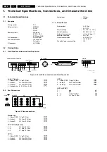
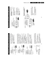
Страница 2: ...rol Figure 1 1 Front Side connections and Front Top control Audio Video In 1 Video CVBS 1 Vpp 75 Ohm 2 Audio L 0 2 Vrms 10 kOhm 3 Audio R 0 2 Vrms 10 kOhm 4 Headphone 8 600 Ohm 4 mW 1 2 2 Rear Connections Figure 1 2 Rear connections Monitor Out 1 Video CVBS 1 Vpp 75 Ohm 2 Audio L 0 5 Vrms 1 kOhm 3 Audio R 0 5 Vrms 1 kOhm AV1 YUV In if present 1 Y 0 7 Vpp 75 Ohm 2 U 0 7 Vpp 75 Ohm 3 V 0 7 Vpp 75 Oh...

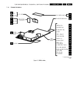
Страница 3: ...9 A10 A11 A8 A13 POWER SUPPLY Q1 FRONT INTERFACE PANEL LINE DEFLECTION FRAME DEFLECTION A6 SYNCHRONISATION TUNER IF VIDEO SOUND IF FRONT I O FRONT CONTROL HEADPHONE BTSC NDBX DECODER A7 CONTROL µC NICAM 2CS BTSC DECODER A V SOURCE SWITCHING AUDIO AMPLIFIER REAR I O CINCH CL 36532118_004 eps 140303 A16 TILT INTERFACE TOP CONTROL PANEL SLIM CRT PANEL W DAF PANEL M MATRIX SURROUND PANEL CRT SCAVEM WI...

Страница 4: ...When the set is used under normal circumstances for example in a living room the recommended interval is three to five years When the set is used in an environment with higher dust grease or moisture levels for example in a kitchen the recommended interval is one year The maintenance inspection includes the following actions 1 Perform the general repair instruction noted above 2 Clean the power su...

Страница 5: ...ed in the Electrical Replacement Parts List Therefore always check this list when there is any doubt 2 4 3 Practical Service Precautions It makes sense to avoid exposure to electrical shock While some sources are expected to have a possible dangerous impact others of quite high potential are of limited current and are sometimes held in less regard Always respect voltages While some may not be dang...

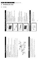
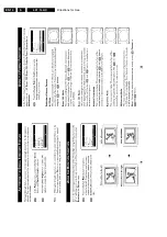
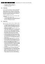
Страница 6: ...Directions for Use EN 6 L01 1L AC 3 3 Directions for Use 3 1 16 9 Sets ...

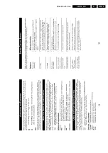
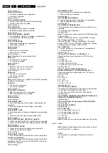
Страница 7: ...Directions for Use EN 7 L01 1L AC 3 ...

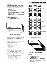
Страница 8: ...Directions for Use EN 8 L01 1L AC 3 ...

Страница 9: ...Directions for Use EN 9 L01 1L AC 3 ...

Страница 10: ...Directions for Use EN 10 L01 1L AC 3 ...

Страница 11: ...Directions for Use EN 11 L01 1L AC 3 ...

Страница 12: ...Directions for Use EN 12 L01 1L AC 3 ...

Страница 13: ...Directions for Use EN 13 L01 1L AC 3 ...

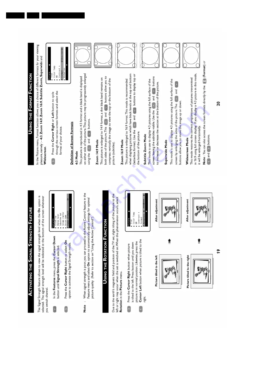
Страница 14: ...Directions for Use EN 14 L01 1L AC 3 ...

Страница 15: ...Directions for Use EN 15 L01 1L AC 3 ...

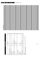
Страница 16: ...Directions for Use EN 16 L01 1L AC 3 Personal Notes ...

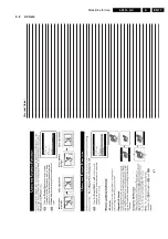
Страница 17: ...Directions for Use EN 17 L01 1L AC 3 3 2 4 3 Sets Personal Notes ...

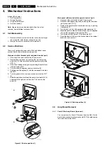
Страница 18: ...nel 90 degrees 4 with the components towards the CRT 6 Turn the panel with its rear connections towards the CRT 5 7 Slide the metal heatsink near the mains transformer 5520 underneath the right chassis bracket This secures the panel 6 Figure 4 1 Service position 1 Main panel with bracket with separate control part 1 Disconnect the strain relief of the AC power cord 2 Disconnect the degaussing coil...

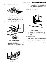
Страница 19: ...present Figure 4 5 DAF panel removal 1 You can remove the complete module from the Main Carrier bracket by pressing its fixation clamp downwards 1 while sliding the module in the direction of the CRT 2 2 Release the 2 fixation clamps 3 to lift the board out of the bracket 4 4 3 5 Side I O Assy Board if present Figure 4 6 Side jack panel removal 1 You can remove the complete Side I O assembly after...

Страница 20: ... the error code buffer To override SW protections To perform alignments To start the blinking LED procedure Specifications Tuning frequency 61 25 MHz channel 3 for NTSC sets LATAM Color system PAL M for LATAM BI TRI FOUR NORMA All picture settings at 50 brightness color contrast hue Bass treble and balance at 50 volume at 25 All service unfriendly modes if present are disabled like Sleep timer Chi...

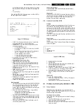
Страница 21: ... settings To store settings leave the SDAM mode with the Standby button on the remote How to exit Switch the set to STANDBY by pressing the power button on the remote control if you switch the set off by removing the AC power the set will return in SDAM when AC power is re applied The error buffer is not cleared 5 2 2 Customer Service Mode CSM Purpose When a customer is having problems with his TV...

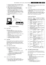
Страница 22: ... care of this ComPair speeds up the repair time since it can automatically communicate with the chassis when the microprocessor is working and all repair information is directly available When ComPair is installed together with the SearchMan electronic manual of the defective chassis schematics and PWBs are only a mouse click away 5 4 2 Specifications ComPair consists of a Windows based faultfindi...

Страница 23: ...buffer is cleared in the following cases By activation of the CLEAR command in the SDAM menu If the content of the error buffer has not changed for 50 hours it resets automatically Note When leaving SDAM by disconnecting the set from AC power the error buffer is not reset 5 4 8 Error Codes In case of non intermittent faults clear the error buffer before you begin the repair These to ensure that ol...

Страница 24: ...s 0 V The reason why the voltage on these pins is so high is because the output driver pin 6 has an open load That is why MOSFET 7521 is not able to switch Reason feedback resistor 3523 is defective Caution be careful measuring on the gate of 7521 circuitry is very high ohmic and can easily be damaged Set is in hiccup mode and shuts down after 8 s Blinking LED set in SDM mode indicates error 5 As ...

Страница 25: ...0 1 probe to one of the cathodes of the picture tube socket see diagram B 9 Measure the cut off pulse during first full line after the frame blanking see Fig 8 2 You will see two pulses one being the cut off pulse and the other being the white drive pulse Choose the one with the lowest value this is the cut off pulse 10 Select the cathode with the highest Vdc value for the alignment Adjust the Vcu...

Страница 26: ...P53 CVI OP54 AV3 OP55 AV2 OP56 AV1 OP57 NTSC_PLAYBACK Option Byte 6 OB6 OP60 BASS_TREBLE OP61 SMART_TEXT OP62 SMART_LOCK OP63 VCHIP LATAM NAFTA Txt_1pg EU Typenumber OP1 OP2 OP3 OP4 OP5 OP6 OP7 28PW6532 44R 16 223 159 226 127 85 64 28PW6532 55R 16 223 159 226 127 85 64 28PW6532 77R 16 223 159 226 127 85 64 28PW6532 78R 16 223 159 226 127 85 64 32PW6532 44R 16 223 159 226 127 85 64 32PW6532 55R 16 ...

Страница 27: ...t applicable 1 Contrast is enabled Default setting 0 OP23 TILT 0 Rotate Picture is disabled or not applicable 1 Rotate Picture is enabled Default setting 0 OP24 NOISE_REDUCTION 0 Noise Reduction NR is disabled or not applicable 1 Noise Reduction NR is enabled Default setting 0 OP25 CHANNEL_NAMING 0 Name FM Channel is disabled or not applicable 1 Name FM Channel is enabled Default setting 0 Note Na...

Страница 28: ...Smart Clock Using PBS is disabled or not applicable 1 Smart Clock Using Teletext and Smart Clock Using PBS is enabled For NAFTA menu item AUTOCHRON is present in the INSTALL submenu Default setting 0 OP66 SMART_SURF 0 Smart Surf feature is disabled or not applicable 1 Smart Surf feature is enabled Default setting 0 OP67 PERSONAL_ZAPPING 0 Personal Zapping feature is disabled or not applicable 1 Pe...

Страница 29: ... settings NORMAL color temperature 9600 K NORMAL R 40 NORMAL G 40 NORMAL B 40 8 3 4 Geometry The geometry alignments menu contains several items to align the set in order to obtain a correct picture geometry Connect an external video pattern generator to the aerial input of the TV set and input a crosshatch test pattern Set the generator amplitude to at least 1 mV and set frequency to 61 25 MHz ch...

Страница 30: ...litude alignment if necessary Vertical Zoom VX The vertical zoom is added in for the purpose of development It helps the designer to set a proper values for the movie expand or movie 16x9 compress Default value is 25 In the table below you will find the GEOMETRY default values for the different sets Table 8 3 Default geometry values 8 3 5 Audio Figure 8 9 Audio alignment menu No alignments are nee...

Страница 31: ...ge source The chassis has a hot ground reference on the primary side and a cold ground reference on the secondary side of the power supply and the rest of the chassis 9 2 Audio Signal Processing 9 2 1 Stereo In stereo sets the signal goes via the SAW filter position 1002 1003 to the audio demodulator part of the UOC IC 7200 The audio output on pin 33 goes to the stereo decoder 7831 7861 The switch...

Страница 32: ...Demodulation The color decoder circuit detects whether the signal is a PAL NTSC or SECAM signal The result is made known to the auto system manager The PAL NTSC decoder has an internal clock generator which is stabilized to the required frequency by using the 12 MHz clock signal from the reference oscillator of the microcontroller teletext decoder The base band delay line is used to obtain a good ...

Страница 33: ...ope the spot is delayed and the slope becomes steeper At the end of the slope the Scavem current decays to zero and the spot is at the original position An overshoot occurs which improves the impression of sharpness At the negative slope the Scavem current counteracts the deflection During the first half of the slope the spot is delayed and the slope becomes steeper During the second half the spot...

Страница 34: ...7 is used R3485 and C2459 ensure that L5457 does not excite because of its own parasite capacitance This L5457 is called the linearity coil The Mannheim Effect When clear white lines are displayed the high voltage circuit is heavily loaded During the first half of the flyback the high voltage capacitors are considerable charged At that point in time the deflection coil excites through C2465 This c...

Страница 35: ...s of the LOT are monitored by the EHTinformation lines These lines are fed to the video processor part of the UOC IC 7200 on pins 11 and 34 This circuit will shut off the horizontal drive in case of over voltage or excessive beam current Figure 9 6 Derived voltages Degaussing When the set is switched on the degaussing relay 1515 is immediately activated as transistor 7580 is conducting Due to the ...

Страница 36: ...r characteristics below The frequency characteristic is not only output power but also input voltage dependent The higher the input voltage the smaller t_prim so the higher the frequency will be Figure 9 8 QR frequency behavior Point P1 is the minimum frequency f_min that occurs at the specified minimum input voltage and maximum output power required by the application Of course the minimum freque...

Страница 37: ...ly a short time and for a longer time inactive waiting for the next burst cycle In the active period the energy is transferred to the secondary and stored in the buffer capacitor C_stab in front of the linear stabilizer see figure below During the inactive period the load e g microprocessor discharges this capacitor In this mode the controller makes use of the Safe Restart mode Figure 9 11 Supply ...

Страница 38: ...value of R3522 The current information is used to adjust the peak drain current which is measured via pin I_sense Short Winding Protection If the sense voltage on pin 5 exceeds the short winding protection voltage 0 75 V the converter will stop switching Once V_cc drops below the UVLO level capacitor C2521 will be recharged and the supply will start again This cycle will be repeated until the shor...

Страница 39: ...d goes to high 3 3 V under standby and fault conditions POWER_DOWN This signal is generated by the power supply Under normal operating conditions this signal is high 3 3 V During standby mode this signal is a pulse train of approx 10 Hz and a high duration of 5 ms It is used to give information to the UOC about the fault condition in the Audio amplifier supply circuit This information is generated...

Страница 40: ...ulation HA Horizontal Acquisition horizontal sync pulse coming out of the HIP HFB Horizontal Flyback Pulse horizontal sync pulse from large signal deflection HP Headphone Hue Color phase control for NTSC not the same as Tint I Monochrome TV system Sound carrier distance is 6 0 MHz I2 C Integrated IC bus IF Intermediate Frequency IIC Integrated IC bus Interlaced Scan mode where two fields are used ...

Страница 41: ...timate One Chip VA Vertical Acquisition VBAT Main supply voltage for the deflection stage mostly 141 V V chip Violence Chip VCR Video Cassette Recorder WYSIWYR What You See Is What You Record record selection that follows main picture and sound XTAL Quartz crystal YC Luminance Y and Chrominance C signal 9 9 IC Data Sheets In this paragraph the internal block diagrams and pinning are given of ICs t...

Страница 42: ...Spare Parts List EN 82 L01 1L AC 10 10 Spare Parts List Not applicable yet ...

Страница 43: ...Revision List EN 83 L01 1L AC 11 11 Revision List First release ...

Отзывы: